Optical reader having a plurality of imaging modules

a technology of optical readers and imaging modules, applied in the field of optical readers, can solve the problems of reducing the overall depth of field of the optical reader, reducing and rendering the modern reader more susceptible to specular reflection read failures, etc., and achieve the effect of improving the overall depth of field

Inactive Publication Date: 2005-12-22
HAND HELD PRODS
View PDF99 Cites 106 Cited by
  • Summary
  • Abstract
  • Description
  • Claims
  • Application Information

AI Technical Summary

Benefits of technology

[0011] A control circuit of the invention can be adapted to carry out a variety of routines involving coordinated capture of image data utilizing more than one imaging module. In one example of the invention, a frame of image data is captured by actuation of a first imaging module and light sources from a first imaging module. The frame is then subjected to a decoding attempt. If the decoding attempt involving the first captured frame fails, a second frame of image data is captured by actuation of an image sensor of the first imaging module and actuation of a light source from a second imaging module and subjected to decoding. The second frame of image data captured utilizing a spaced apart illumination light source and image sensor from two spaced apart imaging modules can be expected to be free of image degradation problems attributable to specular reflection.
[0012] In another aspect of the invention, a control circuit can be configured to combine image data captured by a reader of the invention having more than one imaging module. Because the relative positions of imaging modules in a multiple imaging module reader of the invention are known, first and second frames of image data captured via actuation of first and second imaging modules of a reader of the invention can readily be combined according to an image frame combination method.
[0013] In a still further aspect of the invention, various imaging modules of a multiple imaging module optical reader can be configured to have different best focus positions. Configuring different imaging modules of a multiple imaging module optical reader to have different best focus positions improves the overall depth of field of the multiple imaging module optical reader.

Problems solved by technology

Specular reflection can result in the captured image data failing to exhibit adequate contrast between dark and light markings of a decodable indicia.
With the increased miniaturization of optical readers, light sources for illuminating a target are being positioned in closer proximity with a photodetector element of the reader, thereby rendering the modern reader more susceptible to specular reflection read failures.
The proliferation of the use of decodable markings has brought to light additional problems with presently available optical readers.
Commercially available optical readers cannot easily read high density extra wide decodable symbols or multiple symbols from a scene which are encoded in high density.

Method used


Image

  • Optical reader having a plurality of imaging modules
  • Optical reader having a plurality of imaging modules
  • Optical reader having a plurality of imaging modules

Examples


Embodiment Construction

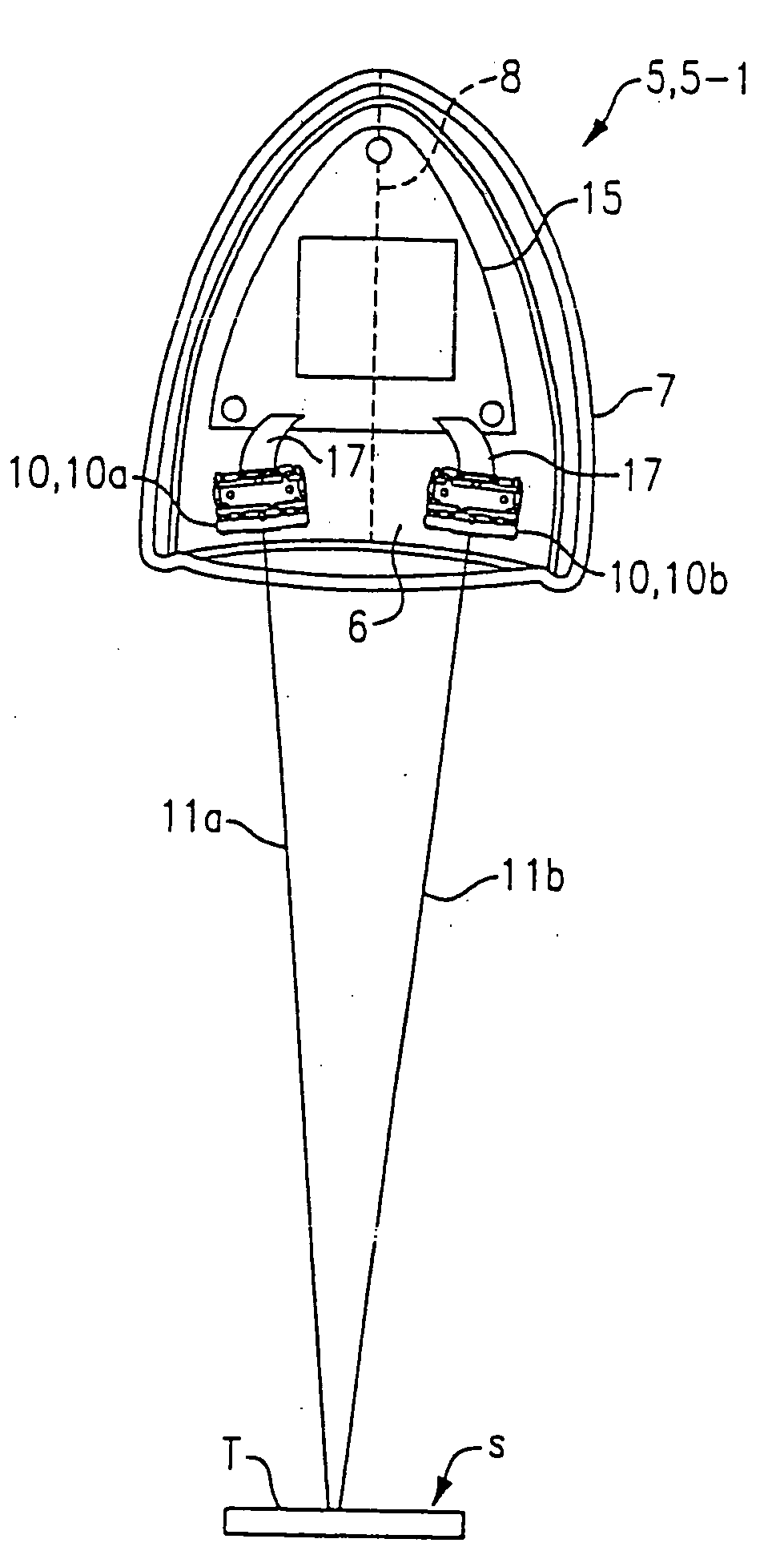
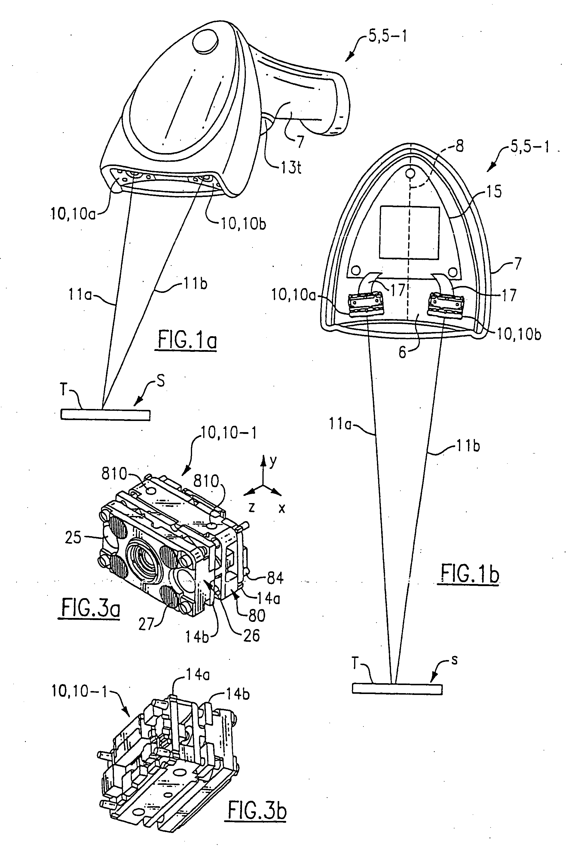
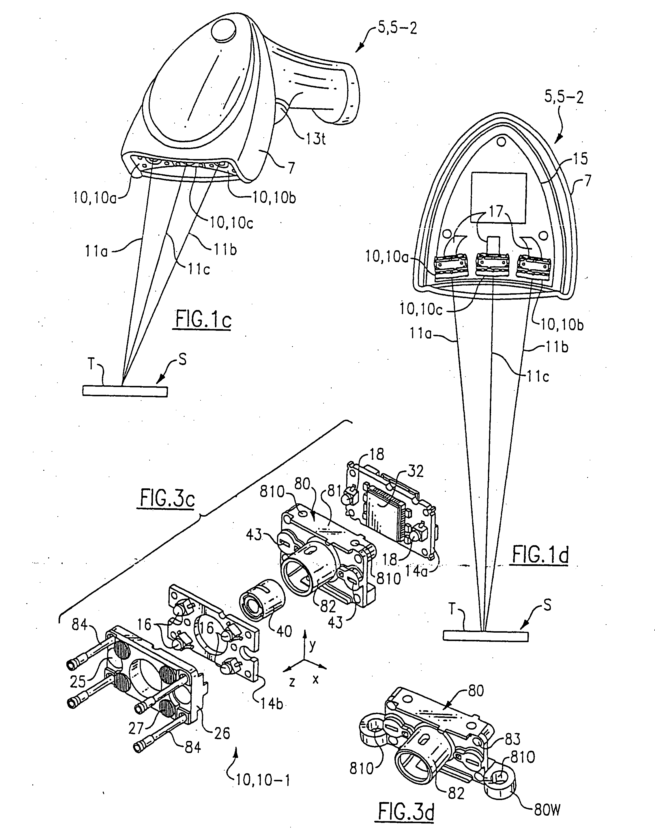
[0032] Embodiments of optical readers having more than one imaging module are shown in FIGS. 1a-1l. In FIGS. 1a-1b a gun style optical reader 5-1 is shown including first and second imaging modules 10a and 10b incorporated in housing 7. Imaging modules 10 can be of the type shown in FIGS. 3a-3d. Imaging module 10, 10-1 as shown in FIGS. 3a and 3c includes a support assembly 80 having a containment section 81 and a retainer section 82, a first circuit board 14a carrying an image sensor 32, a second circuit board 14b, illumination LEDs 16 aiming LEDs 18, an optical plate 26 carrying aiming and illumination optics 25, 27, and support posts 84 holding the various components of the module together. Image sensor 32 as shown in FIGS. 1a-1e includes an area array of photosensitive elements, such as an area (RO) photodiode array. Further details of imaging module 10-1 are described in application Ser. No. 10 / 092,789, filed Mar. 7, 2002, entitled “Optical Reader Imaging Module,” incorporated ...


PUM


Abstract

The invention is an optical reader having a plurality of imaging modules. In one method for operating a multiple imaging module reader of the invention, a second frame of image data captured via actuation of a second imaging module is automatically captured and subjected to decoding in the case an attempt to decode using a frame of image data captured via actuation of a first imaging module fails. In another embodiment, a frame of image data captured via actuation of an image sensor of a first module and actuation of illumination of a second imaging module is subjected to decoding. In another embodiment, frames of image data captured via actuation of image sensors of spaced apart modules are combined. The various modules of a multiple imaging module reader can be adapted to have different best focus positions so that a field depth of the reader is improved.

Description

CROSS-REFERENCE TO RELATED APPLICATIONS [0001] The present application is a continuation of U.S. patent application Ser. No. 10 / 453,796 filed Jun. 3, 2003 entitled, “Optical Reader Having A Plurality Of Imaging Modules” (Attorney Docket No. 283-358.02), which is a continuation in part of U.S. patent application Ser. No. 10 / 161,950 filed Jun. 4, 2002 entitled, “Optical Reader Having A Plurality Of Imaging Modules” (Attorney Docket No. 283-358). This application is also a continuation in part of U.S. patent application Ser. No. 10 / 782,569 filed Feb. 19, 2004 entitled “Optical Reader Having A Plurality Of Imaging Modules” (Attorney Docket No. 283-358 Con) which is a continuation of the aforementioned U.S. patent application Ser. No. 10 / 161,950 filed Jun. 4, 2002 entitled, “Optical Reader Having A Plurality Of Imaging Modules” (Attorney Docket No. 283-358). The present application is also related to U.S. patent application Ser. No. 10 / 440,729 filed May 19, 2003 entitled, “Long Range Opt...

Claims


Application Information

Patent Timeline
Patent Type & Authority Applications(United States)
IPC IPC(8): G06K7/10G06K7/14
CPCG06K7/10574G06K7/10584G06K7/10722G06K7/10861G06K7/1417G06K7/109G06K7/1098G06K7/14G06K7/10881G06V10/17
Inventor HAVENS, WILLIAM H.BARBER, CHARLES P.GANNON, COLLENGARDINER, ROBERT C.HENNICK, ROBERT J.PETTINELLI, JOHN A.
Owner HAND HELD PRODS
Why Eureka
Try Eureka