Antenna and antenna array

a technology applied in the field of antenna array and antenna, can solve the problems of single frequency band no longer meeting the market requirement, and the inability of antennas to provide a single frequency band for their operation

Inactive Publication Date: 2005-12-22
ACCTON TECHNOLOGY CORPORATION
View PDF6 Cites 46 Cited by
  • Summary
  • Abstract
  • Description
  • Claims
  • Application Information

AI Technical Summary

Problems solved by technology

Further, these conventional antennas can only provide a single frequency band for its operation.
As the market grows and the technology advances, a single frequency band no longer can meet the market requirement.

Method used


Image

  • Antenna and antenna array
  • Antenna and antenna array
  • Antenna and antenna array

Examples


Embodiment Construction

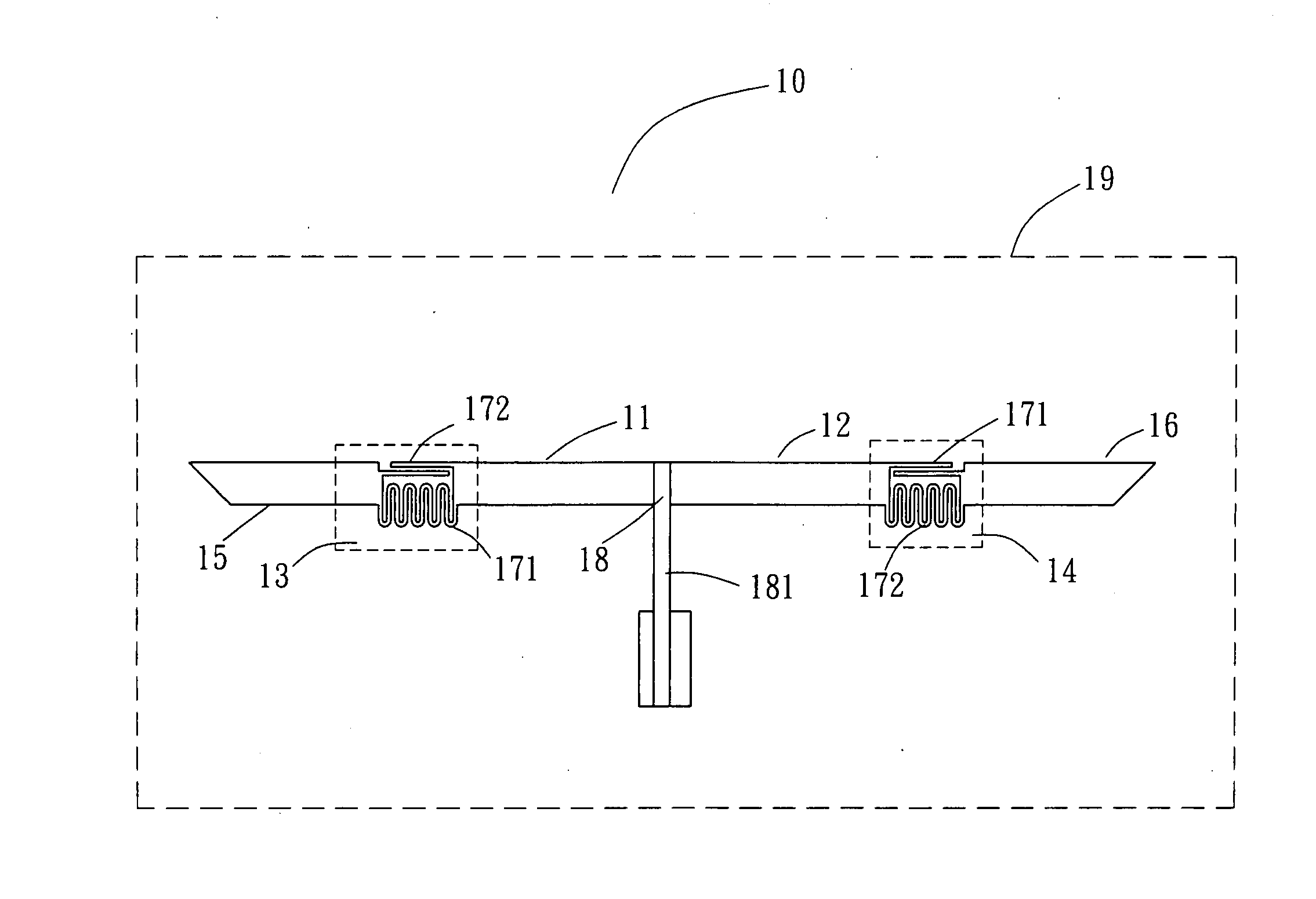
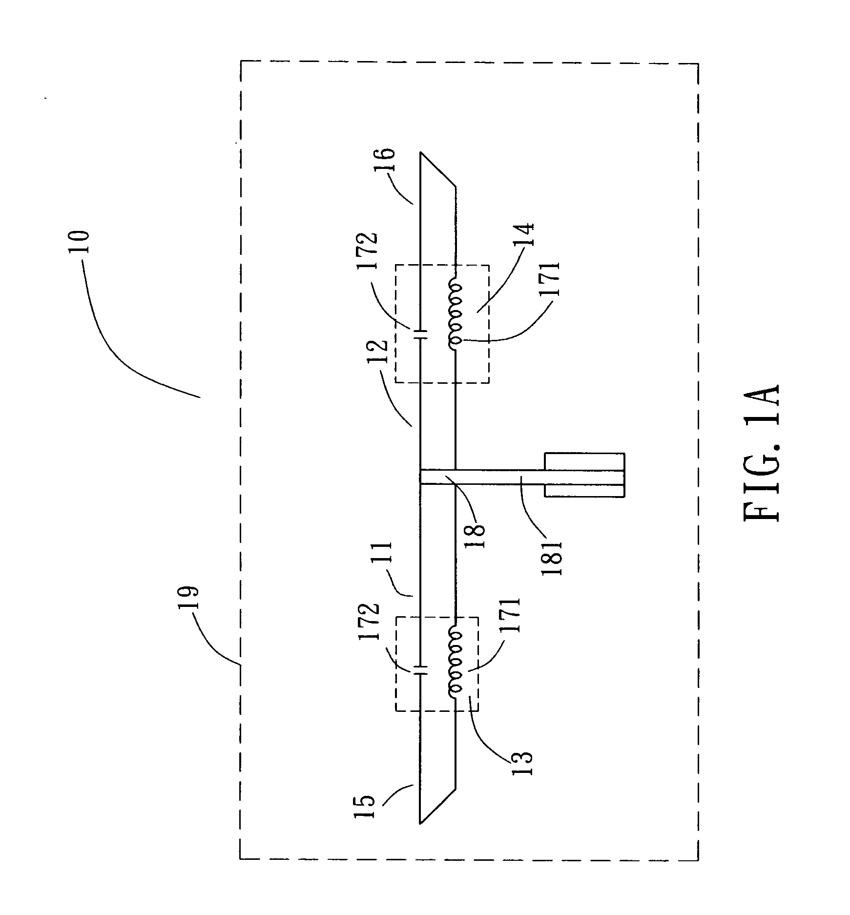
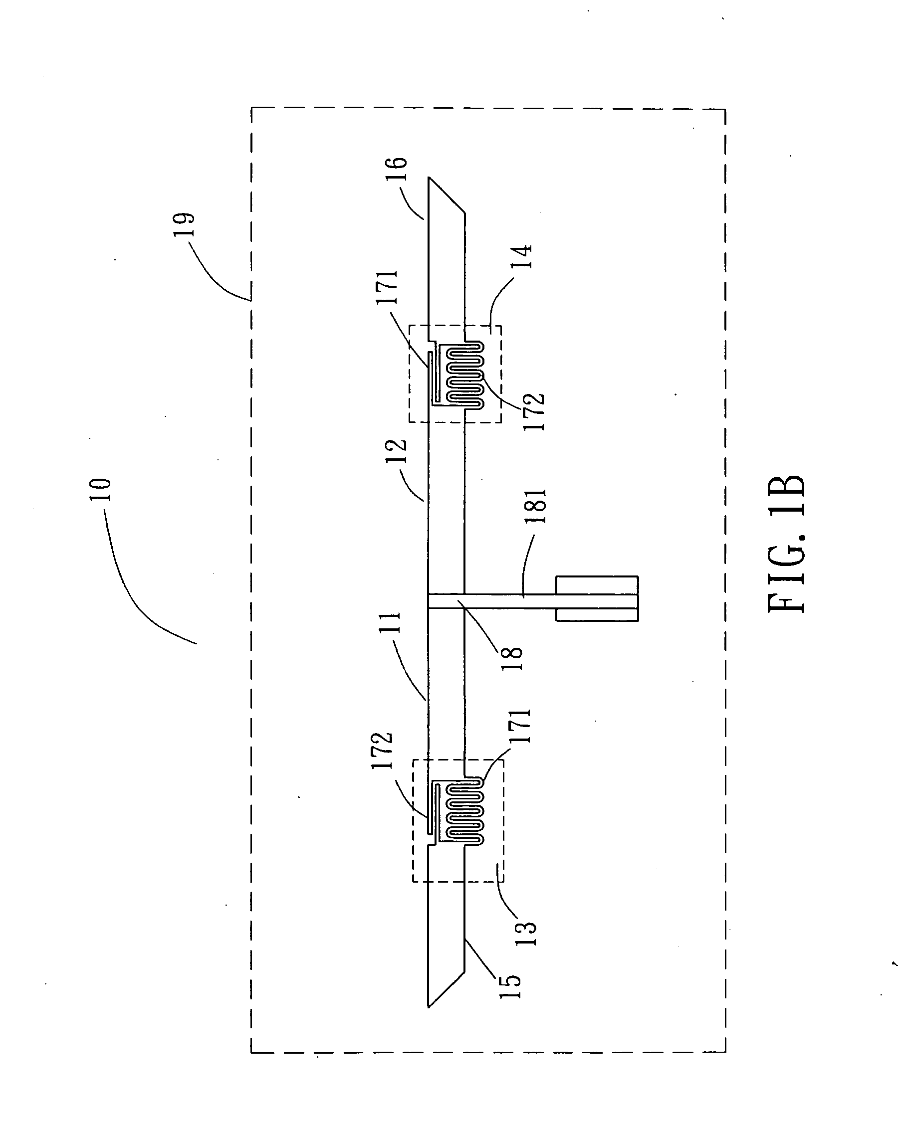
[0014] Please refer to FIGS. 1A and 1B for the illustrative views of the antenna according to a preferred embodiment of the present invention. The antenna 10 is substantially a dipole antenna, comprising a substrate 19, a first dual-frequency antenna 11, a second dual-frequency antenna 12, a first frequency select switch 13, a second frequency select switch 14 and a feed end 18. The substrate 19 is substantially either a printed circuit board made of fiberglass reinforced epoxy resin (FR4) or bismaleimide-triazine (BT), or a flexible film substrate made of polyimide. The first dual-frequency antenna 11 and the second dual-frequency antenna 12 are metal conductive wires printed on the substrate 19, which are symmetrically disposed on the substrate 19. The first frequency select switch 13 has a first end and a second end, and the first end is connected to the first dual-frequency antenna 11 and the second end is connected to a first radiating conductive wire 15. The second frequency s...


PUM


Abstract

The present invention discloses an antenna comprising a substrate, a first dual-frequency antenna, a second dual-frequency antenna, a first frequency select switch, a second frequency select switch and a feed end, wherein the first and the second dual-frequency antennas are disposed on the substrate, and the first frequency select switch has a first end connected to the first dual-frequency antenna and a second end connected to a first radiating conductive wire, and the second frequency select switch has a first end connected to the second dual-frequency antennas and a second end connected to a second radiating conductive wire, and the feed end is disposed between the first dual-frequency antenna and the second dual-frequency antenna. The present invention also discloses an antenna array comprising a substrate, two dual-frequency antenna pairs and a feed structure; wherein the two dual-frequency antenna pairs are installed on the substrate correspondently and the feed part is connected between the two dual-frequency antenna pairs.

Description

1.FIELD OF THE INVENTION [0001] The present invention relates to an antenna and an antenna array, and more particularly, to an antenna and antenna array that can be operated at two different frequency bands. 2.BACKGROUND OF THE INVENTION [0002] As the wireless communications industry blooms, the fast development of wireless transmissions brings in various products and technologies that are used in multiple-frequency transmissions. Thus, many products are equipped with the wireless transmission capability to meet consumer requirements. In addition, it is very important for a wireless transmission product to have a good antenna. [0003] In general, conventional antennas for wireless transmission products are divided into two types: Planar Inverted F Antenna (PIFA) and dual-frequency dipole antenna, and both types have an operating mode that resonates at ¼ wavelength. Further, these conventional antennas can only provide a single frequency band for its operation. As the market grows and...

Claims


Application Information

Patent Timeline
Patent Type & Authority Applications(United States)
IPC IPC(8): H01Q1/38H01Q5/00H01Q5/321H01Q9/36H01Q11/14H01Q21/06H01Q21/29
CPCH01Q1/38H01Q9/36H01Q5/321H01Q21/062H01Q21/29H01Q11/14
Inventor LIANG, JIA-HAURTSAI, TING-YI
Owner ACCTON TECHNOLOGY CORPORATION
Why Eureka
Try Eureka