Method and apparatus to control an antenna efficiency test device

Active Publication Date: 2005-12-22
SAMSUNG ELECTRONICS CO LTD
View PDF7 Cites 2 Cited by
  • Summary
  • Abstract
  • Description
  • Claims
  • Application Information

AI Technical Summary

Benefits of technology

[0013] To attain the advantages and in accordance with the purpose of the invention, as embodied and broadly described herein, method for determining the efficiency of a test antenna is provided. The method comprises measuring an input resistance of an antenna to be tested. Once the input resistance is determined, the antenna is positioned in the test cavity. Next, the input resistance at a given frequency is determined.

Problems solved by technology

Because power input to the antenna is known, and power radiated from the antenna is measurable, power loss is derivable.
Some of the drawbacks are that the test is relatively expensive and time consuming.
However, it has its own drawbacks despite all these novel features.
In particular, the Cavity Method of Efficiency has constraints on the bandwidth of the measurement.
This in turn

Method used


Image

  • Method and apparatus to control an antenna efficiency test device
  • Method and apparatus to control an antenna efficiency test device
  • Method and apparatus to control an antenna efficiency test device

Examples


Embodiment Construction

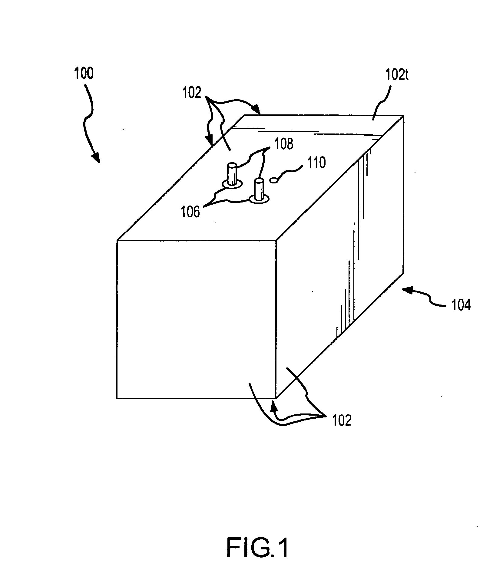
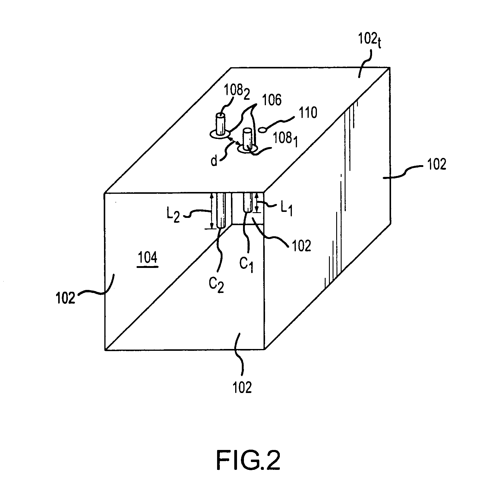
[0024] This invention provides, among other things, a novel test cavity design for the Cavity Method of Efficiency. This novel test cavity enhances the scope of applicability of Cavity Method of Efficiency and improves the accuracy of the measurement. Further, the novel test cavity increases the bandwidth of the measurement range. This invention also proposes and demonstrates that it is possible to use the novel test cavity to carry out the measurement with different types of antennas across many frequency bands of interest. One particular and significant improvement of the novel test cavity of the present invention involves avoidance of the anti resonance and associated negative values of efficiency that result from attempting to take measurements in the anti resonance bandwidth. As will be described, this technical advantage is achieved by the novel test cavity of the present invention in part by minimizing the coupling between the test antenna and the measurement cavity.

[0025] T...


PUM


Abstract

The present invention provides a method to measure antenna efficiency using the cavity method. In particular, the present invention provides a tunable cavity that can be tuned to avoid the anti resonance and antenna-cavity coupling problems. In particular, tuning probes and/or variable volumetric sizing of the cavity are used to tune the cavity to avoid the anti resonance and antenna-cavity coupling.

Description

[0001] This application is related to co-pending application filed herewith under attorney docket number 38105.830084.US0. FIELD OF THE INVENTION [0002] The present invention relates to antenna testing devices and, more particularly, to a cavity test device capable of measuring antenna efficiency. BACKGROUND OF THE INVENTION [0003] One important performance attribute of an antenna is the antenna's radiation efficiency. One way to define or identify an antenna's radiation efficiency is as a ratio of the power radiated from the antenna to the power input to the antenna. The ratio indicates losses in the antenna system. Formula (1), below, defines radiation efficiency η of an antenna as: η=PRPR+PL(1) where PR is the radiated power, and PL is the power loss of the antenna. The quantity PR+PL is the power input to the antenna. Because power input to the antenna is known, and power radiated from the antenna is measurable, power loss is derivable. [0004] An equivalent definition of effici...

Claims


Application Information

Patent Timeline
IPC IPC(8): G01R1/00G01R29/10
CPCG01R29/105
Inventor KADAMBI, GOVIND R.NARAYANAN, RAM M.HUANG, YEQINEVERT, GORDONWINTER, JAMES BLAKE
Owner SAMSUNG ELECTRONICS CO LTD
Why Eureka
Try Eureka