
Large aperture wide-angle lens and camera including large aperture wide-angle lens

a large aperture, wide-angle lens technology, applied in the field of compact large-angle wide-angle lenses, can solve the problems of difficult continuous imaging in order to secure the time required for stroboscopic exposure, inability to produce images as bright as those seen by the human eye, and inability to produce bright images. bright, the effect of small lens diameter, short back focus

Inactive Publication Date: 2005-12-22
FUJI PHOTO OPTICAL CO LTD
View PDF4 Cites 15 Cited by
  • Summary
  • Abstract
  • Description
  • Claims
  • Application Information

AI Technical Summary

Benefits of technology

[0010] The present invention relates to a large aperture wide-angle lens of compact construction, with a small number of lens components and lens elements, with a small lens diameter and a short back focus, with a wider angle of view, with improved brightness, and with excellent performance. The present invention further relates to a camera using such a large aperture wide-angle lens as an imaging lens.

Problems solved by technology

However, with compact cameras using an image pickup device, such as a CCD, it is difficult to produce a picture of a bright image which is the same as the image viewed by the human eye, even with high performance imaging capabilities, and the desired objective has not been achieved.
However, distant objects are not adequately lit in stroboscopic lighting arrangements, and therefore images as bright as those seen by the human eye cannot be produced.
Furthermore, in the case of stroboscopic arrangements, there is also the problem that continuous imaging is difficult in order to secure the time required for stroboscopic exposures.
However, it is known that the improvement of the sensitivity and graininess of a silver salt film has a so-called inverse proportional relationship, that is, as the film sensitivity is increased, improving brightness of an image, the image becomes grainier, creating a rough appearance that is unattractive.
Additionally, the image becomes less sharp and problems in color reproduction occur, making it difficult to achieve the desired objective mentioned above of producing an image that looks the same as when the scene is viewed directly by the human eye.

Method used


Image

  • Large aperture wide-angle lens and camera including large aperture wide-angle lens
  • Large aperture wide-angle lens and camera including large aperture wide-angle lens
  • Large aperture wide-angle lens and camera including large aperture wide-angle lens

Examples


embodiment 1

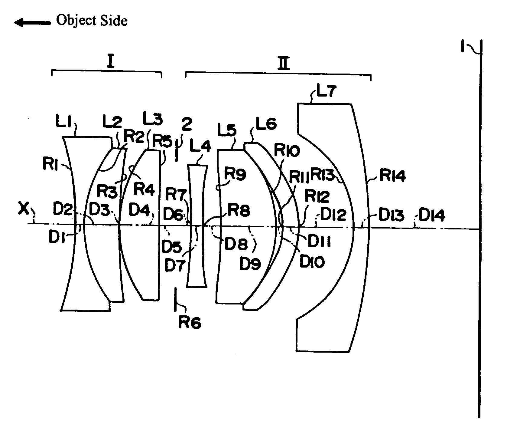
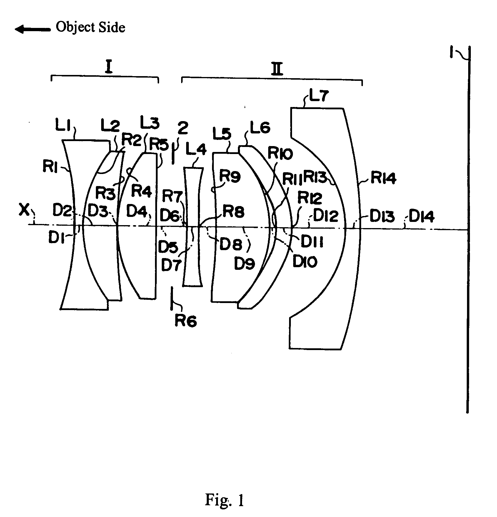
[0047]FIG. 1 shows a cross-sectional view of the large aperture wide-angle lens of Embodiment 1 of the present invention. As shown in FIG. 1, the large aperture wide-angle lens of Embodiment 1 includes, in order from the object side, the first lens group I, the stop 2, and the second lens group II. In order from the object side, the first lens group I includes three lens elements, L1, L2, and L3, and the second lens group II includes four lens elements, L4, L5, L6, and L7. A luminous flux that enters from the object side is efficiently focused on an image plane 1 of FIG. 1, where a photographic film may be located.

[0048] Within the first lens group I, the first lens element L1 is a biconcave lens element with an image-side surface of greater curvature; the second lens element L2 is a meniscus lens element having positive refractive power, having a convex object-side surface, and joined with the first lens element L1 to form a lens component; and the third lens element L3 is a bicon...

embodiment 2

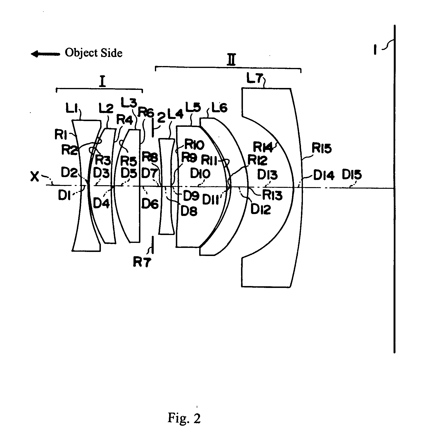
[0057]FIG. 2 shows a cross-sectional view of the large aperture wide-angle lens of Embodiment 2 of the present invention. Embodiment 2 is very similar to Embodiment 1 and uses the same number of lens elements. However, Embodiment 2 differs from Embodiment 1 in that in Embodiment 2, lens elements L1 and L2 are separate lens components rather than joined as one lens component as in Embodiment 1, and Embodiment 2 also differs from Embodiment 1 in that in Embodiment 2, lens element L3 is a meniscus lens element with the convex surface on the object side rather than a biconvex lens element as in Embodiment 1 (but lens element L3 has positive refractive power in both Embodiments 1 and 2).

[0058] Table 4 below lists the surface number # in order from the object side, the radius of curvature R (in mm) of each surface on the optical axis, the on-axis surface spacing D (in mm), as well as the refractive index Nd and the Abbe number νd (both at the d-line of 587.6 nm) of each optical element f...

embodiment 3

[0065]FIG. 3 shows a cross-sectional view of the large aperture wide-angle lens of Embodiment 3 of the present invention. Embodiment 3 is similar to Embodiment 1 and uses the same number of lens elements and lens components. However, Embodiment 3 differs from Embodiment 1 in that in Embodiment 3, lens element L3 is a meniscus lens element with the convex surface on the object side rather than a biconvex lens element as in Embodiment 1 (but lens element L3 has positive refractive power in both Embodiments 1 and 3). Additionally, Embodiment 3 differs from Embodiment 1 in that in Embodiment 3, lens element L5 is a biconvex lens element rather than a meniscus lens element as in Embodiment 1 (but the image-side surface has greater curvature in both Embodiments 1 and 3), and Embodiment 3 differs from Embodiment 1 in that in Embodiment 3, lens element L7 is a biconcave lens element rather than a meniscus lens element as in Embodiment 1 (but the object-side surface has greater curvature in ...


PUM


Abstract

A large aperture wide-angle lens includes first and second lens groups separated by a stop. The first lens group includes more than one lens element and the second lens group includes, in order from the object side, a first lens component having at least one aspheric surface, having negative refractive power, and having increasingly negative refractive power toward the periphery, a second lens component having a convex surface on the image side, and a third lens component having at least one aspheric surface and having decreasingly positive refractive power or increasingly negative refractive power toward the periphery. The large aperture wide-angle lens includes six or seven lens components and seven lens elements, and preferably satisfies specified conditions related to f-number and focal length of the wide-angle lens, the maximum image height at the image surface, and the index of refraction of the object-side lens element of the second lens group.

Description

FIELD OF THE INVENTION [0001] The present invention relates to a compact large aperture wide-angle lens suitable for use as an imaging lens in cameras, particularly photographic cameras using a photosensitive silver salt film. BACKGROUND OF THE INVENTION [0002] In recent years, as a compact camera, a camera using an image pickup device such as a CCD, has become common. In response to the popularity of such cameras, various compact imaging lenses using a relatively small number of lens elements and lens components have been developed. [0003] One ultimate objective in camera development is for a camera that produces a finished image that is the same as the original scene viewed by the human eye. However, with compact cameras using an image pickup device, such as a CCD, it is difficult to produce a picture of a bright image which is the same as the image viewed by the human eye, even with high performance imaging capabilities, and the desired objective has not been achieved. [0004] It ...

Claims


Application Information

Patent Timeline
Patent Type & Authority Applications(United States)
IPC IPC(8): G02B13/04G02B15/14
CPCG02B13/04
Inventor TOYAMA, NOBUAKI
Owner FUJI PHOTO OPTICAL CO LTD
Learn More