Magnetic head for perpendicular magnetic recording and method of manufacturing same

a perpendicular magnetic and magnetic recording technology, applied in the direction of head surface, head with metal sheet core, instruments, etc., can solve the problems of difficult to define the throat height th with accuracy, and the possibility of protruding

Active Publication Date: 2005-12-22
HEADWAY TECH INC
View PDF17 Cites 9 Cited by
  • Summary
  • Abstract
  • Description
  • Claims
  • Application Information

AI Technical Summary

Benefits of technology

[0019] It is an object of the invention to provide a magnetic head for perpendicular magnetic recording having a structure in which a pole layer faces toward a shield layer with a gap layer disposed in between, the head being capable of defining the throat height with accuracy and suppressing protrusion of the medium-facing-surface-side end of the shield layer due to the hear generated by the coil, and to provide a method of manufacturing such a magnetic head.

Problems solved by technology

In a magnetic disk drive of the perpendicular magnetic recording system that exhibits a better capability of writing on a recording medium than the longitudinal magnetic recording system, in particular, if the above-mentioned skew is created, problems arise, such as a phenomenon in which data stored on an adjacent track is erased when data is written on a specific track (that is hereinafter called adjacent track erasing) or unwanted writing is performed on adjacent two tracks.
The first problem of the head of FIG. 17 is that it is difficult to define the throat height TH with accuracy.
The second problem of the head of FIG. 17 is that, when the head is operated, the end of the shield layer 103 located closer to the medium facing surface 100 is likely to protrude, which results from the heat generated by the coil 101.

Method used


Image

  • Magnetic head for perpendicular magnetic recording and method of manufacturing same
  • Magnetic head for perpendicular magnetic recording and method of manufacturing same
  • Magnetic head for perpendicular magnetic recording and method of manufacturing same

Examples


first embodiment

[First Embodiment]

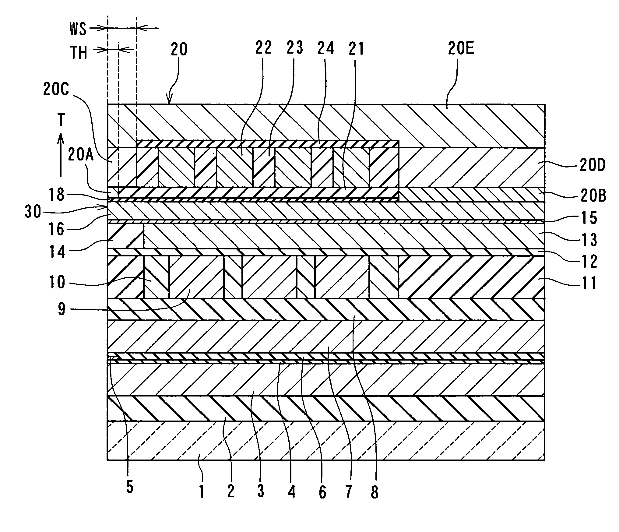
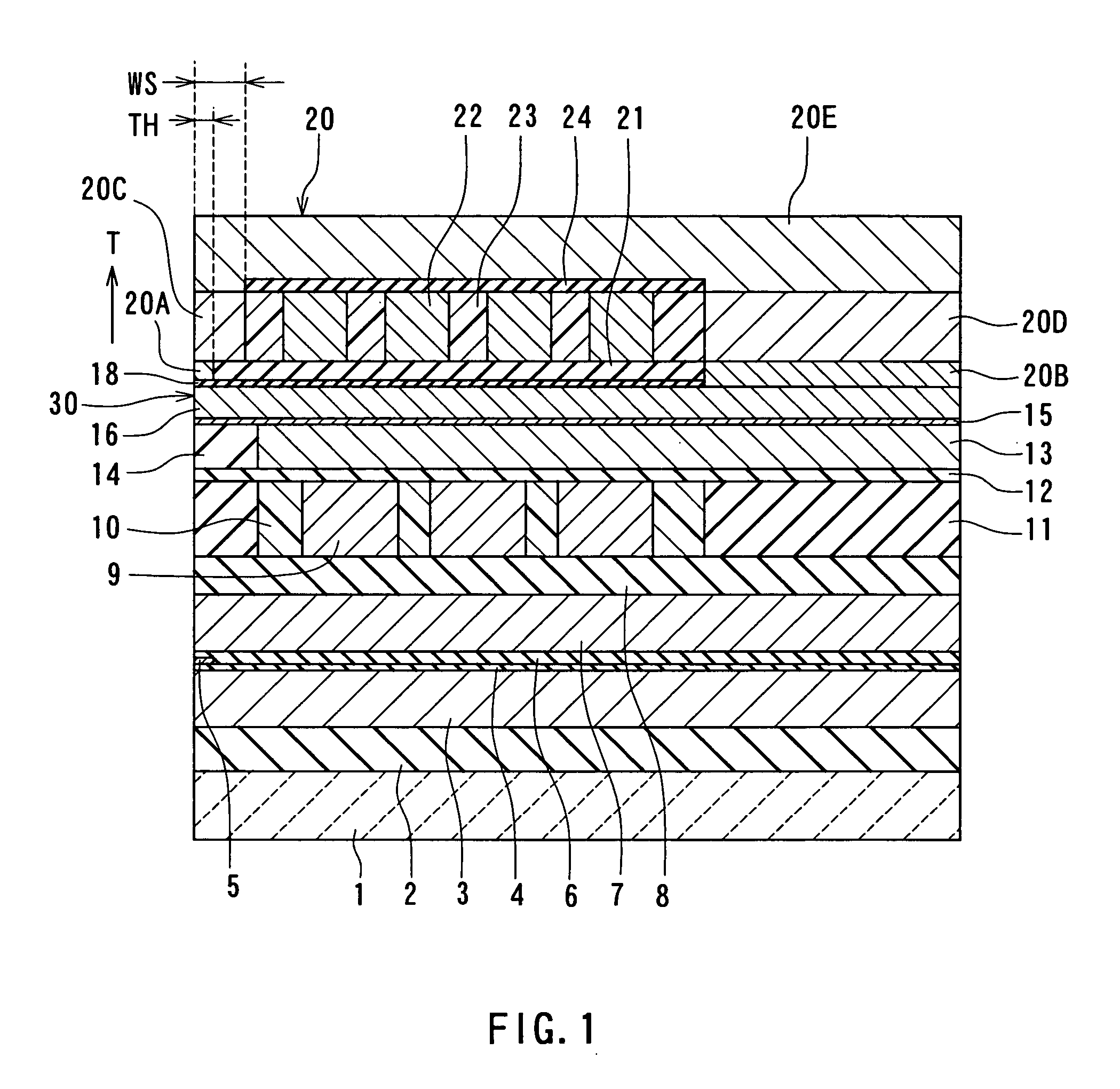
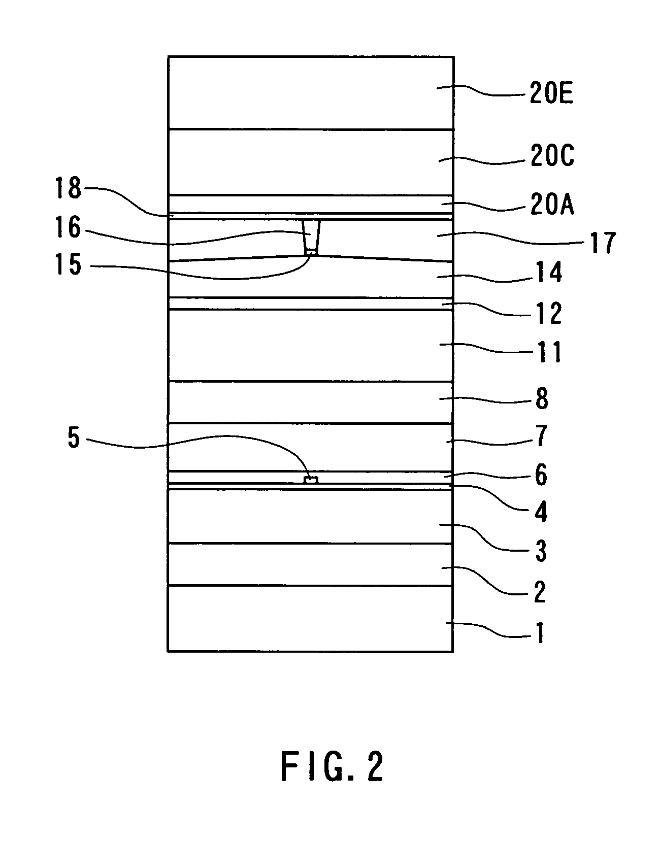
[0048] Preferred embodiments of the invention will now be described in detail with reference to the accompanying drawings. Reference is now made to FIG. 1 and FIG. 2 to describe the configuration of a magnetic head for perpendicular magnetic recording of a first embodiment of the invention. FIG. 1 is a cross-sectional view for illustrating the configuration of the magnetic head of the embodiment. FIG. 1 illustrates a cross section orthogonal to the medium facing surface and a surface of a substrate. The arrow indicated with T in FIG. 1 shows the direction of travel of a recording medium. FIG. 2 is a front view of the medium facing surface of the magnetic head of the embodiment.

[0049] As shown in FIG. 1 and FIG. 2, the magnetic head for perpendicular magnetic recording (hereinafter simply called the magnetic head) of the embodiment comprises: a substrate 1 made of a ceramic such as aluminum oxide and titanium carbide (Al2O3—TiC); an insulating layer 2 made of an in...

second embodiment

[Second Embodiment]

[0091] Reference is now made to FIG. 13A and FIG. 13B to describe a magnetic head and a method of manufacturing the same of a second embodiment of the invention. FIG. 13A is a cross section of the main part of the magnetic head orthogonal to the medium facing surface and the substrate. FIG. 13B is a cross section of a portion of the main part of the magnetic head near the medium facing surface that is parallel to the medium facing surface.

[0092] According to the second embodiment, the magnetic head comprises an insulating layer 41 covering the at least part of the coil in place of the insulating layers 23 and 24 of the first embodiment. According to the second embodiment, the magnetic head comprises a shield layer 40 in place of the shield layer 20 of the first embodiment. The shield layer 40 has a first layer 40A, a coupling layer 40B and a second layer 40C. The first layer 40A has a first end located in the medium facing surface 30 and a second end opposite to ...

third embodiment

[Third Embodiment]

[0098] Reference is now made to FIG. 14A to FIG. 16A and FIG. 14B to FIG. 16B to describe a method of manufacturing a magnetic head of a third embodiment of the invention. FIG. 14A to FIG. 16A are cross sections of layered structures obtained in the course of the manufacturing process orthogonal to the medium facing surface and the substrate. FIG. 14B to FIG. 16B are cross sections of portions of the layered structures near the medium facing surface that are parallel to the medium facing surface. Portions closer to the substrate 1 than the insulating layer 12 are omitted in FIG. 14A to FIG. 16A and FIG. 14B to FIG. 16B.

[0099] The method of manufacturing the magnetic head of the third embodiment includes the steps up to the step of forming the first layer 20A and the coupling layer 20B that are the same as those of the first embodiment.

[0100]FIG. 14A and FIG. 14B illustrate the following step. In the step the nonmagnetic layer 21 is first formed on the entire top ...


PUM

PropertyMeasurementUnit
heightaaaaaaaaaa
saturation flux densityaaaaaaaaaa
thicknessaaaaaaaaaa

Abstract

A magnetic head comprises a pole layer, a gap layer, a shield layer, a nonmagnetic layer, and a coil. The shield layer incorporates: a first layer disposed on the gap layer; a second layer disposed on the first layer; a two layered coupling layer disposed on a region of the pole layer where an opening of the gap layer is formed; and a third layer disposed to couple the second layer to the coupling layer. The first layer defines throat height TH. The nonmagnetic layer is disposed on a side of the first layer. The coil is disposed on the nonmagnetic layer on a side of the second layer.

Description

BACKGROUND OF THE INVENTION [0001] 1. Field of the Invention [0002] The present invention relates to a magnetic head for perpendicular magnetic recording that is used for writing data on a recording medium by using a perpendicular magnetic recording system and to a method of manufacturing such a magnetic head. [0003] 2. Description of the Related Art [0004] The recording systems of magnetic read / write devices include a longitudinal magnetic recording system wherein signals are magnetized in the direction along the surface of the recording medium (the longitudinal direction) and a perpendicular magnetic recording system wherein signals are magnetized in the direction orthogonal to the surface of the recording medium. It is known that the perpendicular magnetic recording system is harder to be affected by thermal fluctuation of the recording medium and capable of implementing higher linear recording density, compared to the longitudinal magnetic recording system. [0005] Magnetic heads...

Claims


Application Information

Patent Timeline
Patent Type & Authority Applications(United States)
IPC IPC(8): G11B5/127G11B5/147G11B5/187G11B5/31
CPCG11B5/1278G11B5/1872G11B5/3163G11B5/3136G11B5/3143G11B5/3106
Inventor SASAKI, YOSHITAKAITOH, HIROYUKILI, DONG-HONGWANG, PO-KANGGUAN, LIJIE
Owner HEADWAY TECH INC
Why Eureka
Try Eureka