Electronic assemblies with high capacity curved and bent fin heat sinks and associated methods

a technology of curved fins and heat sinks, applied in the field of electrical packaging, can solve problems such as catastrophic failure, degrading performance, and increasing operating temperature to unacceptable levels

Inactive Publication Date: 2005-12-22
INTEL CORP
View PDF83 Cites 27 Cited by
  • Summary
  • Abstract
  • Description
  • Claims
  • Application Information

AI Technical Summary

Benefits of technology

[0141] The inventive subject matter provides for a heat sink and an electronic assembly that minimize thermal dissipation problems associated with high power delivery, and to methods of manufacture thereof. An electronic system and / or data processing system that incorporates one or more electronic assemblies that utilize the inventive subject matter can handle the relatively high power densities associated with high performance integrated circuits, and such systems are therefore more commercially attractive.
[0142] By substantially increasing the thermal dissipation from high performance electronic assemblies, such electronic equipment can be operated at increased clock frequencies. Alternatively, such equipment can be operated at reduced clock frequencies but with lower operating temperatures for increased reliability.

Problems solved by technology

As the internal circuitry of ICs, such as processors, operates at higher and higher clock frequencies, and as ICs operate at higher and higher power levels, the amount of heat generated by such ICs can increase their operating temperature to unacceptable levels, degrading their performance or even causing catastrophic failure.
However, with high-performance ICs consuming ever greater amounts of power and accordingly producing greater amounts of heat, heat dissipation equipment must have higher heat dissipation capability than that heretofore obtained.
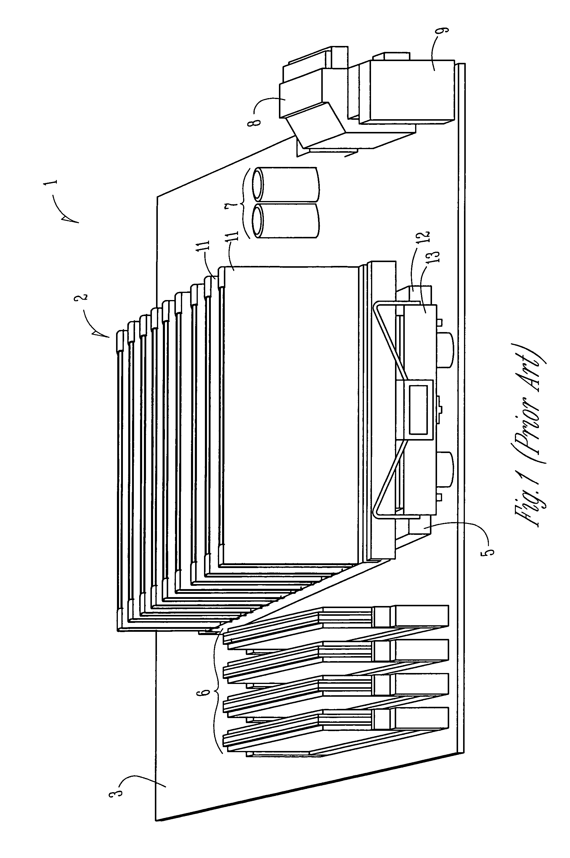
It is difficult for air-cooled heat sinks to grow in size, because equipment manufacturers are under tremendous competitive pressure to maintain or diminish the size of their equipment packages, all the while filling them with more and more components.

Method used


Image

  • Electronic assemblies with high capacity curved and bent fin heat sinks and associated methods
  • Electronic assemblies with high capacity curved and bent fin heat sinks and associated methods
  • Electronic assemblies with high capacity curved and bent fin heat sinks and associated methods

Examples


Embodiment Construction

[0041] In the following detailed description of some exemplary embodiments of the inventive subject matter, reference is made to the accompanying drawings which form a part hereof, and in which is shown by way of illustration, but not of limitation, some specific embodiments in which the inventive subject matter may be practiced, including a preferred embodiment. These embodiments are described in sufficient detail to enable those skilled in the art to understand and practice them, and it is to be understood that other embodiments may be utilized and that structural, mechanical, compositional, and procedural changes may be made without departing from the spirit and scope of the inventive subject matter. The following detailed description is, therefore, not to be taken in a limiting sense, and the scope of embodiments of the inventive subject matter is defined only by the appended claims. Such embodiments of the inventive subject matter may be referred to, individually and / or collect...


PUM

PropertyMeasurementUnit
radiusaaaaaaaaaa
aspect ratioaaaaaaaaaa

Abstract

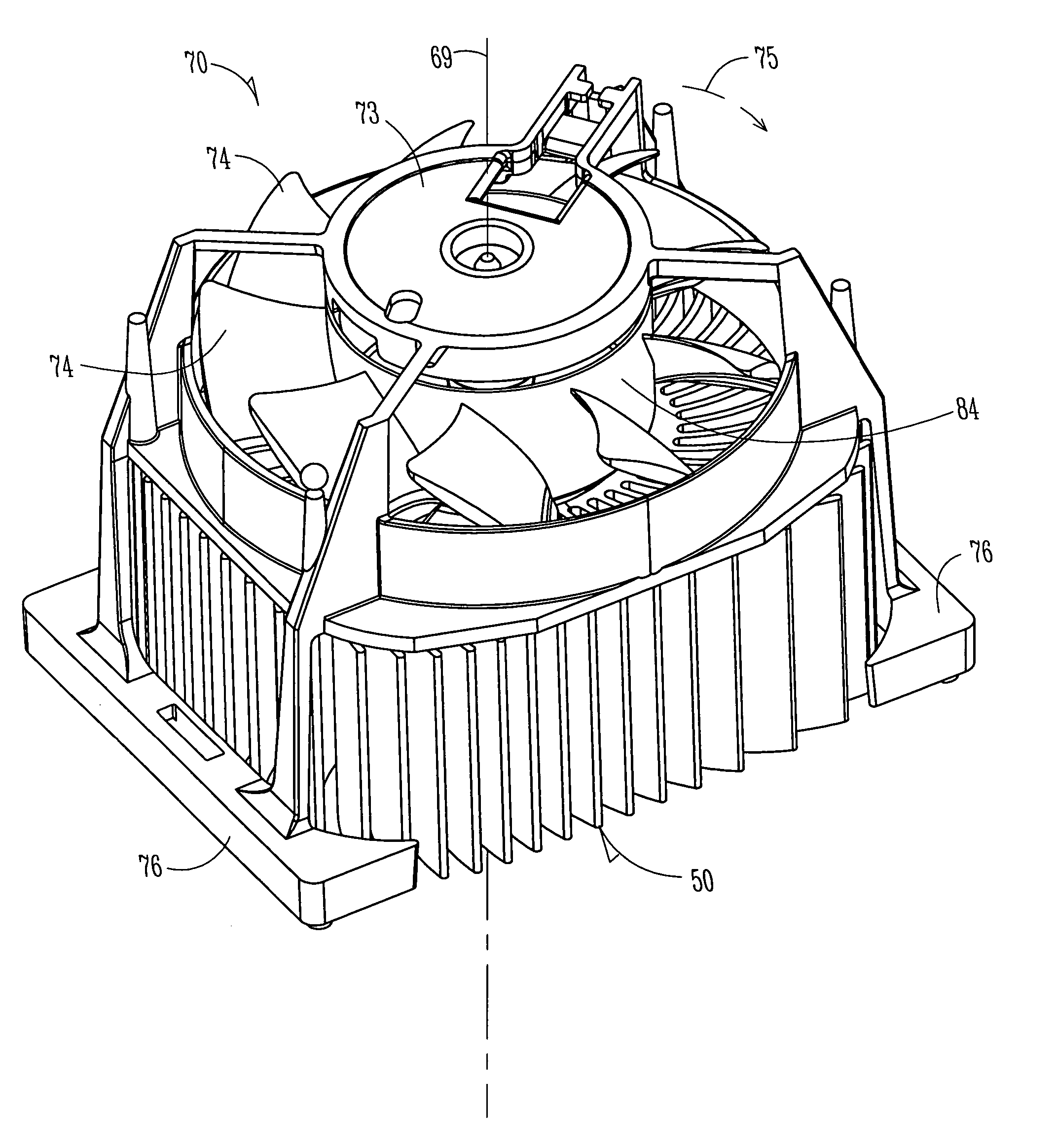
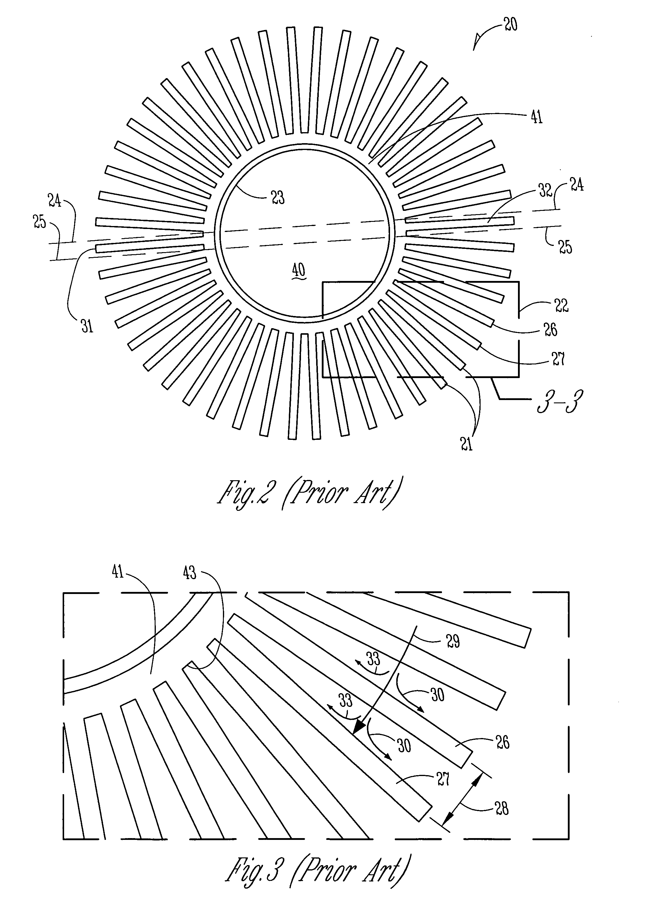
An electronic assembly comprising one or more high performance integrated circuits includes at least one high capacity heat sink. The heat sink, which comprises a number of fins projecting substantially radially from a core, is structured to capture air from a fan and to direct the air to optimize heat transfer from the heat sink. The heat sink fins can be formed in different shapes. In one embodiment, the fins are curved. In another embodiment, the fins are bent. In yet another embodiment, the fins are curved and bent. Methods of fabricating heat sinks and electronic assemblies, as well as application of the heat sink to an electronic assembly and to an electronic system, are also described.

Description

DIVISIONAL APPLICATION [0001] The present application is a divisional of U.S. patent application Ser. No. 10 / 716,764, filed on Nov. 19, 2003, which is a divisional of U.S. patent application Ser. No. 09 / 950,100, filed on Sep. 10, 2001, now U.S. Pat. No. 6,671,172, which are both incorporated herein by reference. RELATED APPLICATIONS [0002] The present application is related to the following applications that are assigned to the same assignee as the present application: [0003] Ser. No. 09 / 716,510, now U.S. Pat. No. 6,633,484, entitled “Heat Dissipating Devices, Systems, and Methods with Small Footprint”; [0004] Ser. No. 09 / 766,757, now U.S. Pat. No. 6,535,385, entitled “High-Performance Heat Sink Configurations For Use In High Density Packaging Applications”; [0005] Ser. No. 09 / 800,120, entitled “Radial Folded Fin Heat Sink”; [0006] Ser. No. 09 / 860,978, now U.S. Pat. No. 6,479,895, entitled “High Performance Air Cooled Heat Sinks Used In High Density Packaging Applications”; [0007] S...

Claims


Application Information

Patent Timeline
Patent Type & Authority Applications(United States)
IPC IPC(8): H01L23/367H01L23/467H05K7/20
CPCH01L23/3672H01L23/467Y10T29/4935H01L2924/0002H01L2924/00
Inventor CARTER, DANIEL P.CROCKER, MICHAEL T.
Owner INTEL CORP
Why Eureka
Try Eureka