Dynamic optimization of efficiency using dead time and FET drive control

a technology of dead time and drive control, applied in the direction of dc-dc conversion, power conversion system, instruments, etc., can solve the problems of increasing cost, not ensuring improvement, maximum efficiency and performance, etc., and achieve the effect of optimizing efficiency and changing the efficiency of the converter

Inactive Publication Date: 2005-12-22
ASTEC INT LTD
View PDF22 Cites 75 Cited by
  • Summary
  • Abstract
  • Description
  • Claims
  • Application Information

AI Technical Summary

Problems solved by technology

Designing such parameters for a specific load, input, output, components, and temperature may improve single design point efficiency but will not result in maximum efficiency and performance at different load and line conditions and will not guarantee improvement at that design point because of the components and temperature variations.
Of course, there are still some disadvantages / challenges in using digital controllers for analog systems such as DC-DC converters in power electronics including the required high resolution needed from the digital controller to satisfy the converter's tight regulation requirements and the required high speed digital controller to satisfy the converter's dynamic requirements.
These two requirements also result in increased cost.
The selection and optimization of this dead time is not an easy task and is difficult to achieve at all load / input conditions and at different components parasitics and temperatures.
This method is simple but unfortunately results in lower efficiency since the dead time has to be set long enough to cover the whole load / input range and to cover other variations such as temperature variations.
However, the body diodes still conduct and losses are still considerable especially at higher switching frequencies and higher output currents.
It is also difficult to implement in isolated topologies because of the delays caused by the isolators used in generating the drive signals and the transformer leakage inductance, which vary at different load and line conditions.

Method used


Image

  • Dynamic optimization of efficiency using dead time and FET drive control
  • Dynamic optimization of efficiency using dead time and FET drive control
  • Dynamic optimization of efficiency using dead time and FET drive control

Examples


Embodiment Construction

[0023] The following description of the preferred embodiment(s) is merely exemplary in nature and is in no way intended to limit the invention, its application, or uses.

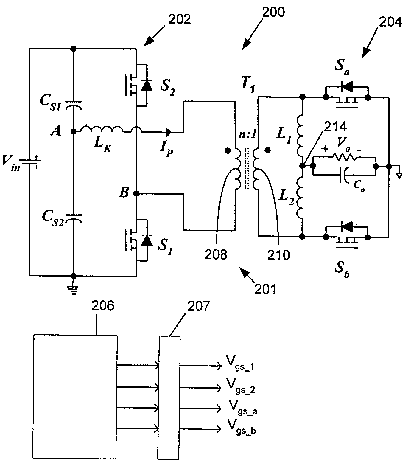
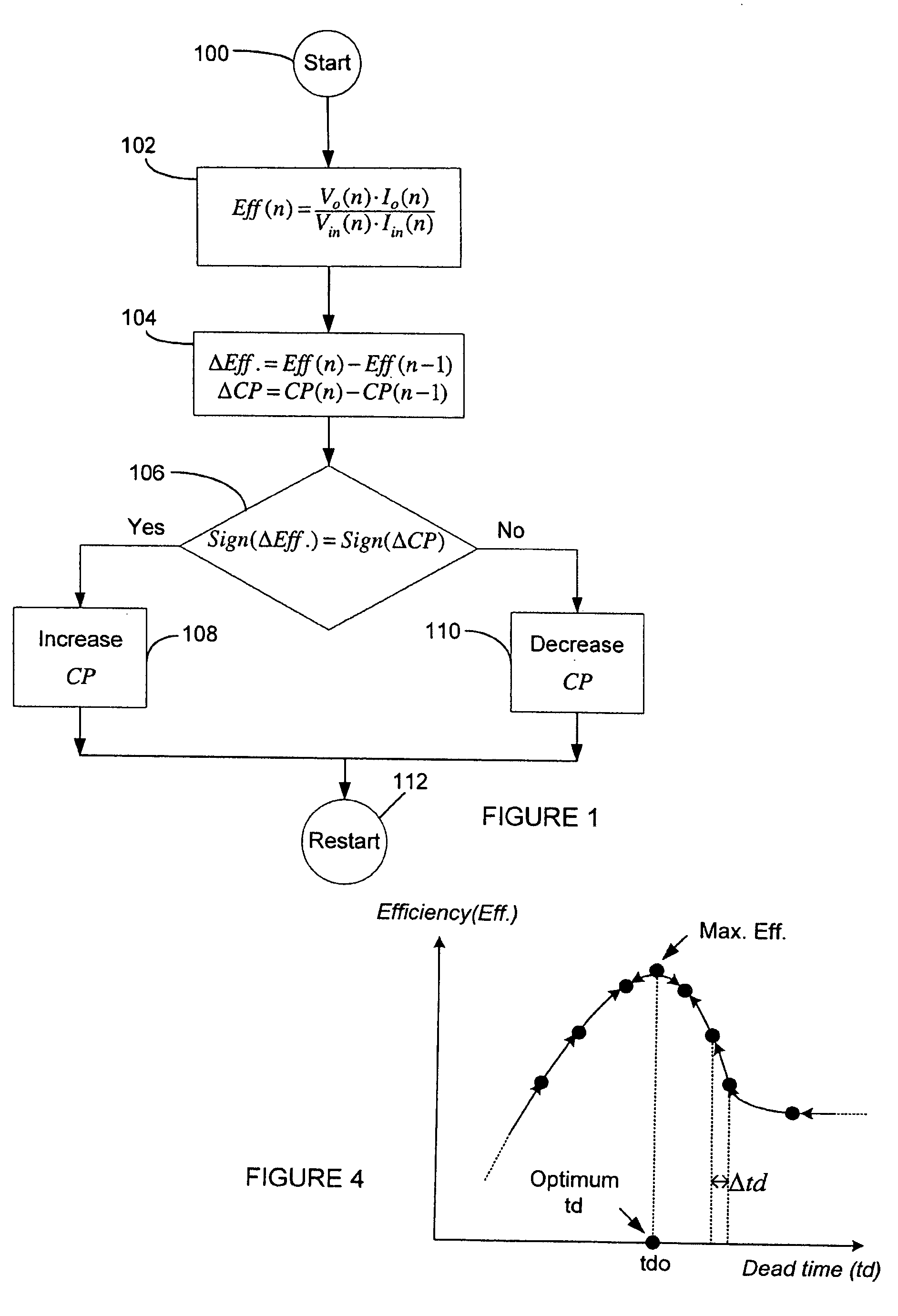
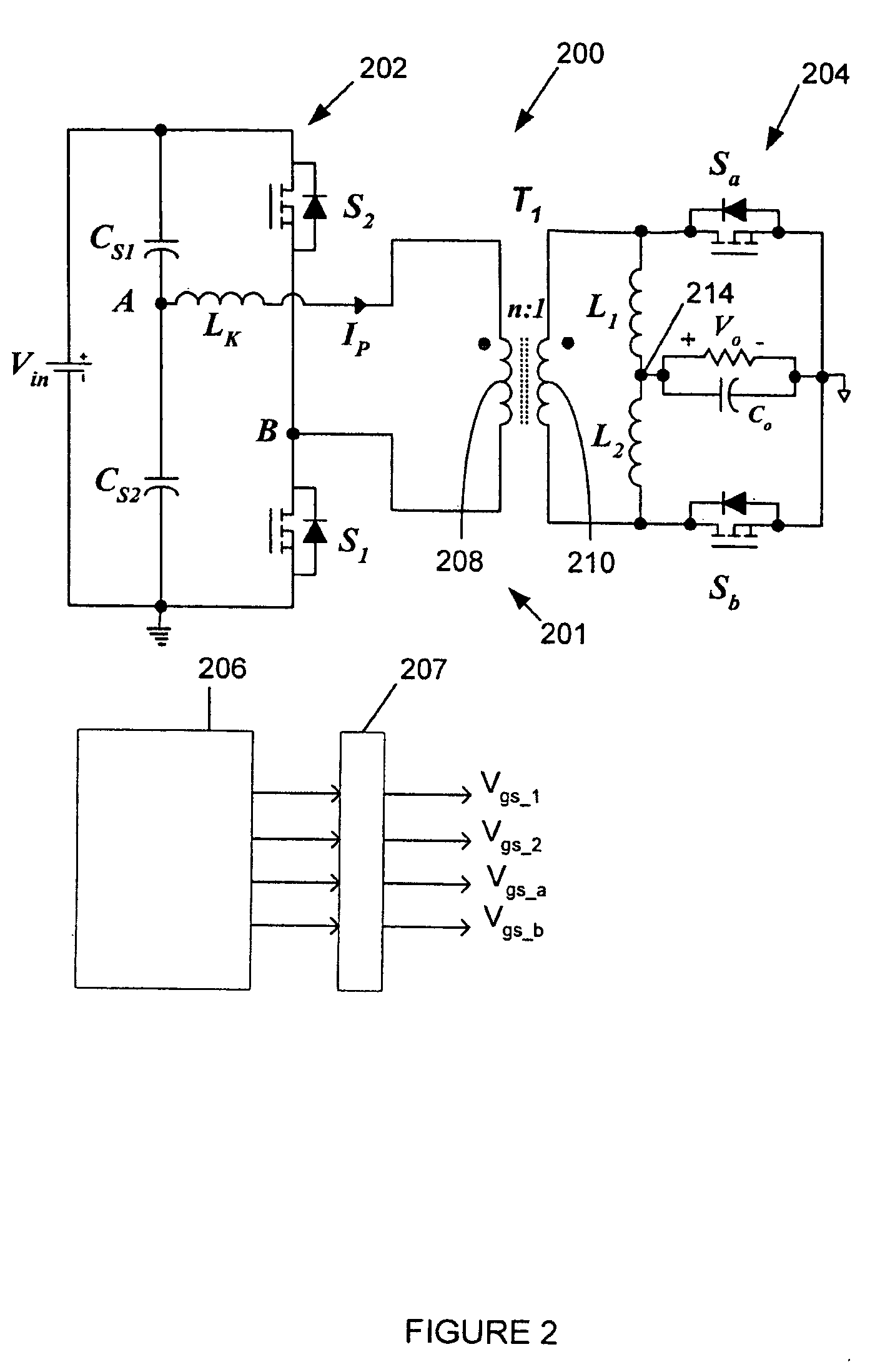
[0024] A method of controlling power converters in accordance with this invention, referred to herein as Maximum Efficiency Point Tracking (“MEPT”), tracks system efficiency and dynamically optimizes one or more system parameters, referred to herein as “controlled parameters” to maximize efficiency, or in other words minimum input power point causing efficiency maximization. In this regard, a system or controlled parameter is a parameter affecting operation of the system that is controlled or varied to optimize efficiency. The inventive MEPT method tracks the efficiency of the converter to find the optimized value of the parameter(s) that are dynamically adjusted by tracking the direction of change of the efficiency (ΔEff.) of the converter, that is, whether it is increasing or decreasing, and the direction of chang...


PUM


Abstract

A power converter uses a control method to optimize efficiency by dynamically optimizing a controlled parameter. A change in efficiency of the converter after changing at least one controlled parameter is determined. The direction of change in efficiency of the converter is compared to a direction of the change in the controlled parameter. The controlled parameter is changed in a positive direction when the direction in the change in the efficiency of the converter and the direction of the change in the controlled parameter are the same and changed in a negative direction when the direction in the change in the efficiency of the converter and the direction of the change in the controlled parameter are opposite. The controlled parameters may include dead time between turn-on and turn-off and between turn-off and turn-on of the primary and corresponding secondary side switches of the controller, drive voltage(s) for the switches, and intermediate bus voltages.

Description

CROSS-REFERENCE TO RELATED APPLICATIONS [0001] This application claims the benefit of U.S. Provisional Application No. 60 / 581,986 filed on Jun. 21, 2004.FIELD OF THE INVENTION [0002] The present invention relates to power converters such as those used in power supplies, and more particularly, using dynamic optimization of efficiency by using maximum efficiency point tracking (or minimum input power point tracking). BACKGROUND OF THE INVENTION [0003] In designing power electronics converter systems such as DC-DC converters, several design parameters need to be optimized to improve the efficiency and converter performance. Some of these parameters are load dependant, input voltage / output voltage dependent, components dependent, and / or temperature dependent. Designing such parameters for a specific load, input, output, components, and temperature may improve single design point efficiency but will not result in maximum efficiency and performance at different load and line conditions an...

Claims


Application Information

Patent Timeline
Patent Type & Authority Applications(United States)
IPC IPC(8): H02M1/38H02M3/335
CPCH02M3/33576H02M1/38
Inventor BATARSEH, ISSAQAHOUQ, JABER ABUMAO, HONG
Owner ASTEC INT LTD
Why Eureka
Try Eureka