Automated recovery from a split segment condition in a layer2 network for teamed network resources of a computer systerm

a network resource and split segment technology, applied in data switching networks, frequency-division multiplexes, instruments, etc., can solve the problems of network failure, bus must be reconnected, network resources are more expensive,

Active Publication Date: 2005-12-22
HEWLETT-PACKARD ENTERPRISE DEV LP
View PDF13 Cites 81 Cited by
  • Summary
  • Abstract
  • Description
  • Claims
  • Application Information

AI Technical Summary

Benefits of technology

[0020] An embodiment of a method of the invention automatically recovers from a split segment condition in which a contiguous layer 2 network segment, including a plurality of contiguous paths each directly coupling one or more members of a team of network resources of a computer system to a core switch of a layer 2 network is split into two or more no...

Problems solved by technology

Of course, the greater the throughput, the more expensive the network resources required to sustain that throughput.
The problem with the bus network approach is that if the interface for one of the devices fails or if one of the devices is removed from the network, the network bus must be reconnected to bypass the missing or malfunctioning device or the network is broken.
As processing speed continues to increase and memory access time continues to decrease for a network device such as a server, the bottleneck for device throughput becomes pronounced at the interface to the network.
While network architectures and associated network adapters are being designed to handle ever-increasing throughput rates, the price for implementing interface resources supporting the highest available throughput is not al...

Method used


Image

  • Automated recovery from a split segment condition in a layer2 network for teamed network resources of a computer systerm
  • Automated recovery from a split segment condition in a layer2 network for teamed network resources of a computer systerm
  • Automated recovery from a split segment condition in a layer2 network for teamed network resources of a computer systerm

Examples


Embodiment Construction

[0039] The following discussion is directed to various embodiments of the invention. Although one or more of these embodiments may be preferred, the embodiments disclosed should not be interpreted as, or otherwise be used for limiting the scope of the disclosure, including the claims, unless otherwise expressly specified herein. In addition, one skilled in the art will understand that the following description has broad application, and the discussion of any particular embodiment is meant only to be exemplary of that embodiment, and not intended to intimate that the scope of the disclosure, including the claims, is limited to that embodiment. For example, while the various embodiments may employ one type of network architecture and / or topology, those of skill in the art will recognize that the invention(s) disclosed herein can be readily applied to all other compatible network architectures and topologies.

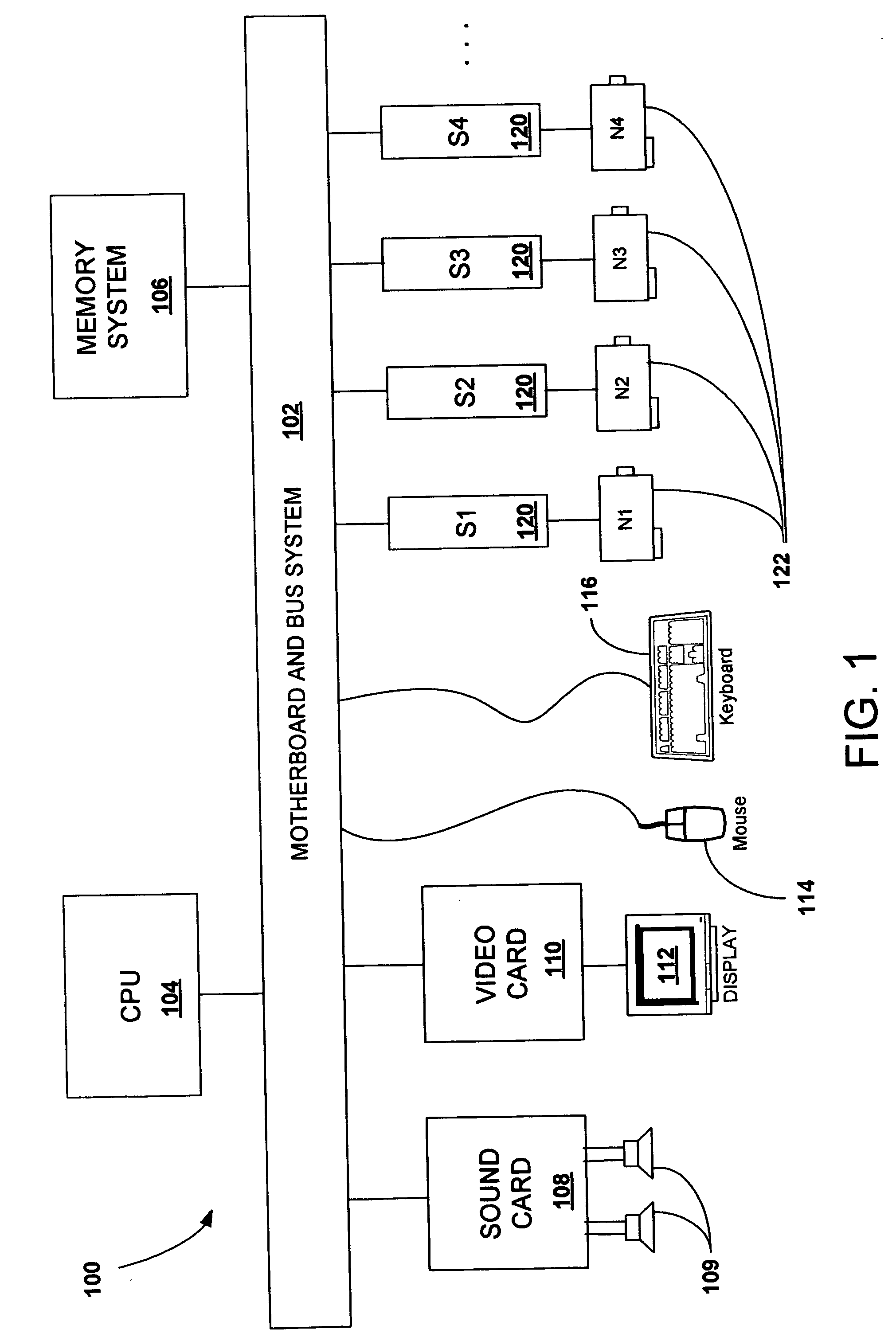
[0040]FIG. 1 is a block diagram of a computer system 100 that illustrates v...


PUM


Abstract

A computer system automatically recovers from a split segment condition in which a contiguous layer 2 network segment, comprising a plurality of contiguous paths each directly coupling one or more members of a team of network resources of the computer system to a core switch of a layer 2 network, is split into two or more noncontiguous segments each comprising a contiguous set of one or more of the plurality of paths. The computer system includes a team of network resources having one or more members that couple it to each one of the plurality of paths. A teaming driver binds the drivers of each member of the team and is coupled to the segment through the members of the team. The teaming driver detects whenever the network segment has been split into two or more noncontiguous segments and then configures the team such that one of the members coupled to a path within each of the noncontiguous segments is designated as a primary resource thereby restoring connectivity of the isolated paths to the computer system.

Description

[0001] This application claims the benefit of U.S. Provisional Application No. 60 / 580,509, filed Jun. 7, 2004.BACKGROUND [0002] Computers and other devices are commonly interconnected to facilitate communication among one another using any one of a number of available standard network architectures and any one of several corresponding and compatible network protocols. The nature of standard architectures and their topologies is typically dictated at the first two layers of the OSI (Open Systems Interconnection) Basic Reference Model for networks, which are the physical layer (layer 1) and the data link layer (layer 2). One of the most commonly employed of such standard architectures is the Ethernet® network architecture. Other types of network architectures that are less widely used include ARCnet, Token Ring and FDDI. Variations of the Ethernet® standard are differentiated from one another based on characteristics such as maximum throughput (i.e. the highest data transmission rate)...

Claims


Application Information

Patent Timeline
IPC IPC(8): H04L12/24H04L12/26H04L12/28H04L12/56
CPCH04L41/0659H04L43/0811H04L45/48H04L45/22H04L45/28H04L45/00
Inventor MCGEE, MICHAEL SEANMCINTYRE, MICHAEL SEANHOWARD, GREGORY THOMAS
Owner HEWLETT-PACKARD ENTERPRISE DEV LP
Why Eureka
Try Eureka