
Vane pump

a technology of vane pump and cover, which is applied in the direction of piston pump, positive displacement liquid engine, liquid fuel engine, etc., can solve the problems of reducing the volume efficiency of the pump, more likely deformation and buckling of the cover, so as to reduce the strength of the thinner portion of the cover

Active Publication Date: 2005-12-22
KYB CORP
View PDF6 Cites 6 Cited by
  • Summary
  • Abstract
  • Description
  • Claims
  • Application Information

AI Technical Summary

Benefits of technology

The present invention provides a vane pump with an iron reinforcing plate that increases the strength of the cover without requiring accurate dimensional control. This reduces distortion of the cover and prevents oil leakage, improving the volume efficiency of the pump. Additionally, the concave portion in the cover is not necessary, as the iron reinforcing plate can be incorporated into the cover without affecting its performance.

Problems solved by technology

And since the contact area between the outer side plate and the cover is small, when the vane pump is used as a high-pressure pump, deformation and buckling of the cover are more likely to occur.
If dimensional accuracy thereof deteriorates, the outer side plate is not maintained to be perpendicular to a drive shaft, so that a clearance is produced between the outer side plate and a cam ring, possibly reducing volume efficiency of the pump.
And when perpendicularity of the outer side plate to the drive shaft is not maintained as described above, metallic contact between the outer side plate and a rotor occurs, possibly causing seizing thereof.

Method used


Image

  • Vane pump
  • Vane pump
  • Vane pump

Examples


Embodiment Construction

[0019] Selected preferred embodiments of the present invention will now be explained with reference to the drawings. It will be apparent to those skilled in the art from this disclosure that the following description of the preferred embodiments of the present invention is provided for illustration only, and not for the purpose of limiting the invention as defined by the appended claims and their equivalents.

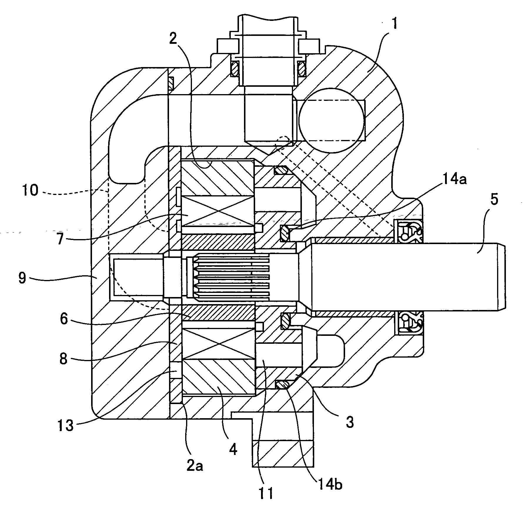
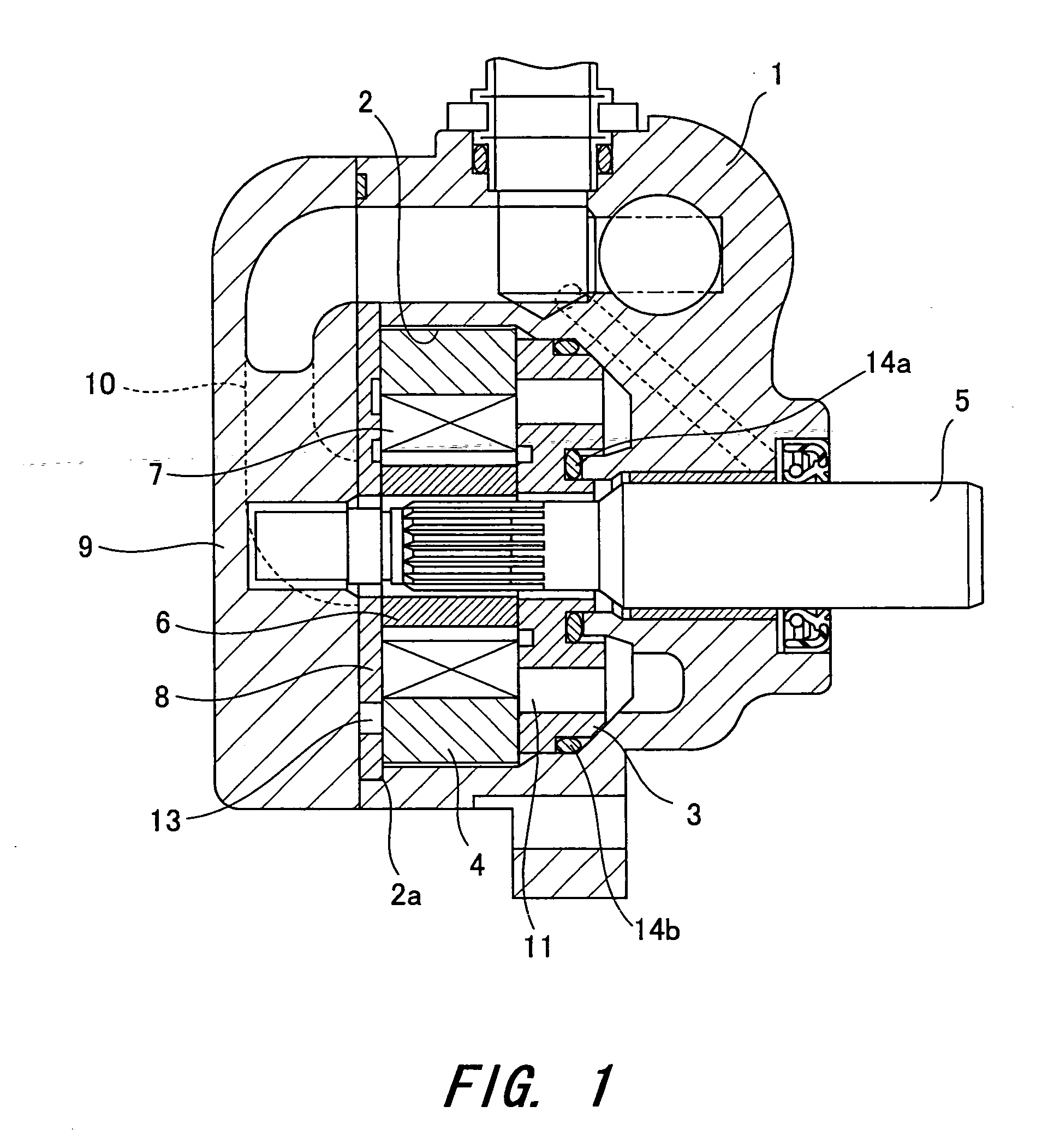
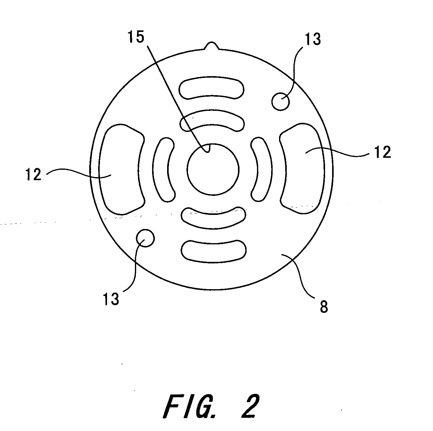
[0020] In a first preferred embodiment shown in FIG. 1 to FIG. 3, a body bore 2 is formed in an aluminum-forged body 1 and an iron side plate 3 and an iron cam ring 4 are incorporated into the body bore 2.

[0021] A drive shaft 5 is provided in the body 1 to go through a center of each of the side plate 3 and the cam ring 4. An iron rotor 6 is provided on the drive shaft 5 in the cam ring 4 to rotate together with the drive shaft 5, and also a plurality of grooves are radially formed on an outer periphery of the rotor 6. Vanes 7 are incorporated into the grooves to move therein ...


PUM


Abstract

A body bore 2 formed in a body 1 is closed with a cover 9, as well as a cam ring 4 is incorporated into the body bore 2, and a rotor 6 is arranged inside the cam ring 4. Vanes 7 move in and out along an inner surface of the cam ring 4 with rotation of the rotor 6. An iron reinforcing plate 8 is interposed inside the body bore 2 between the cam ring 4 and the cover 9.

Description

BACKGROUND OF THE INVENTION [0001] 1. Field of the Invention [0002] The present invention relates to a vane pump. [0003] 2. The Related Art of the Invention [0004] Typically a cover for a vane pump is provided with complicated oil passages at a part of the cover and as a result, strength of the cover itself is possibly damaged. Hence, a conventional pump for the purpose of maintaining the strength of the cover is disclosed in Japanese Unexamined Patent Publication JP7-279871A. [0005] The conventional pump is provided with a concave portion formed at a joint face of the cover to a pump body, and an outer side plate made of iron sintered alloy is fitted into the concave portion as a reinforcing member. The rigidity of a cover side including the outer side plate is maintained by thus incorporating the outer side plate into the concave portion formed in the cover. And the outer side plate also serves to cover groove-shaped oil passages formed in the cover. [0006] Portions of the outer s...

Claims


Application Information

Patent Timeline
Patent Type & Authority Applications(United States)
IPC IPC(8): F04B17/00F04B35/00F04C2/344F04C15/00
CPCF01C21/108F04C2230/22F04C15/0023F04C2/3446
Inventor IDE, NORIKAZUFUJITA, TOMOYUKIIHIRA, HIDEYASU
Owner KYB CORP
Learn More