Transmitting apparatus

a technology of transmitting apparatus and transmission path, which is applied in the direction of transmission monitoring, electromagnetic wave modulation, power management, etc., can solve the problems of large load of signal processing, low calibration accuracy, and inability to meet the requirements of signal processing, so as to reduce the load of signal processing

Inactive Publication Date: 2005-12-22
NEC CORP
View PDF19 Cites 35 Cited by
  • Summary
  • Abstract
  • Description
  • Claims
  • Application Information

AI Technical Summary

Benefits of technology

[0029] It is another object of the present invention to implement, in a transmitting apparatus which forms a transmission directivity pattern by weighting an antenna weight, online (during operation) transmission path calibration to reduce the load of signal processing by adjusting the calibration frequency.

Problems solved by technology

This suppresses the remaining system capacity of carrier power in each transmission path.
Since this requires high-speed arithmetic processing, the load of signal processing is large.
As a result, the calibration signal looks like interference for the user signal more than necessary, and the calibration accuracy is low.
Hence, correction cannot be done in consideration of the saturation characteristic in the constituent element in the transmission path.
As a result, accurate calibration is impossible.
However, even calibration of a transmitting apparatus which executes transmission diversity has the same problems.

Method used


Image

  • Transmitting apparatus
  • Transmitting apparatus
  • Transmitting apparatus

Examples


first embodiment

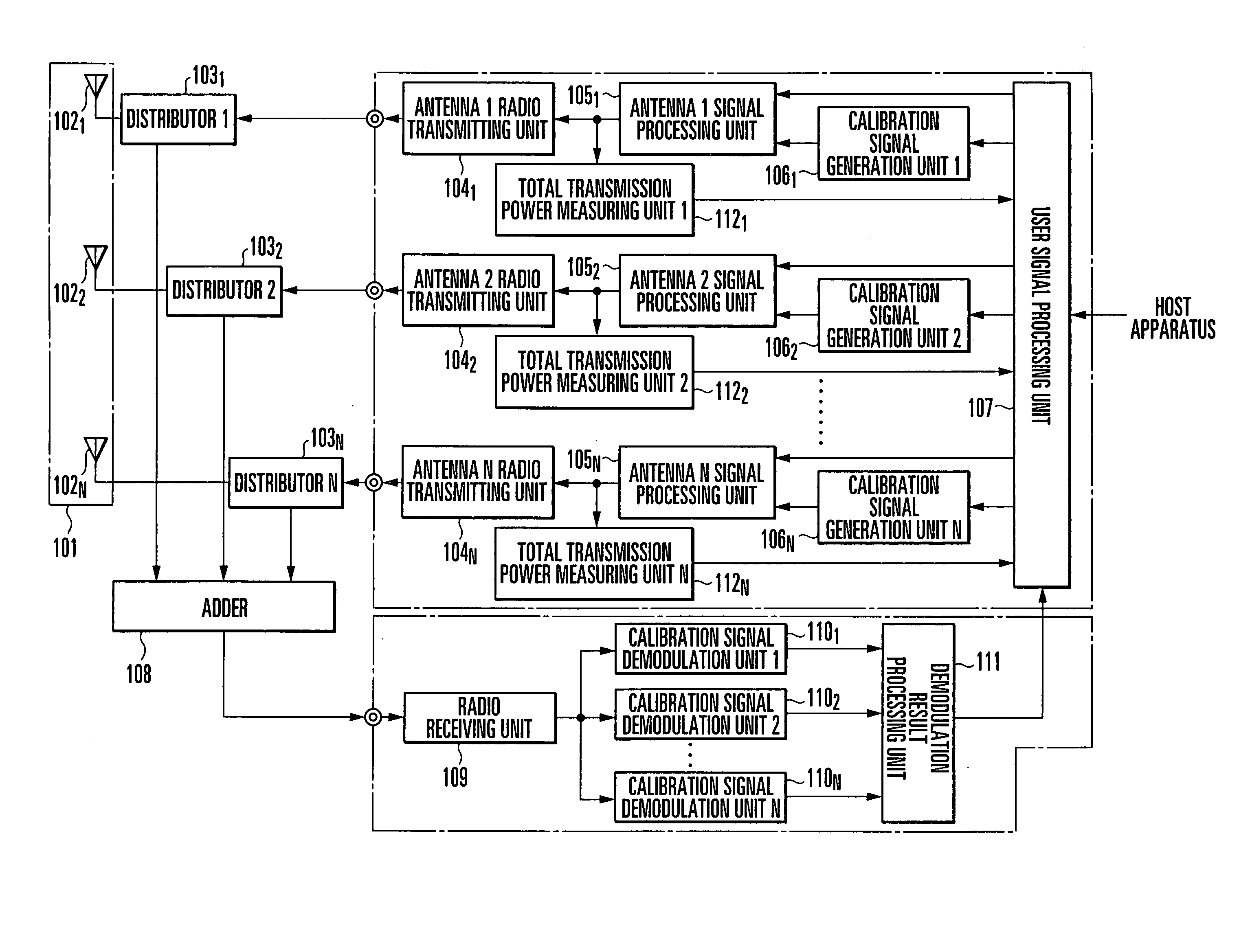
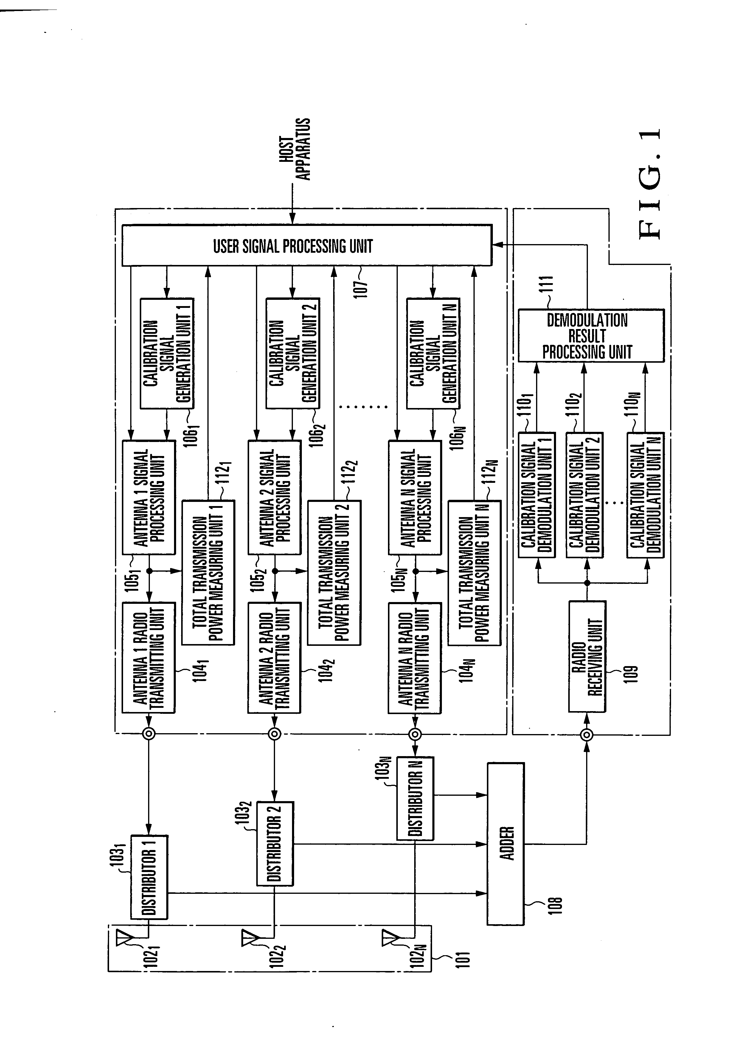
[0045]FIG. 1 shows the arrangement of an array antenna transmitting / receiving apparatus according to the first embodiment of the present invention. This array antenna transmitting / receiving apparatus has a function of executing online calibration. More specifically, the array antenna transmitting / receiving apparatus comprises an array antenna 101 including N antenna elements 1021 to 102N, distributor 11031 to distributor N 103N, antenna 1 radio transmitting unit 1041 to antenna N radio transmitting unit 104N, antenna 1 signal processing unit 1051 to antenna N signal processing unit 105N, calibration signal generation unit 11061 to calibration signal generation unit N 106N, user signal processing unit 107, adder 108, radio receiving unit 109, calibration signal demodulation unit 11101 to calibration signal demodulation unit N 110N, demodulation result processing unit 111, and total transmission power measuring unit 11121 to total transmission power measuring unit N 112N. The transmis...

second embodiment

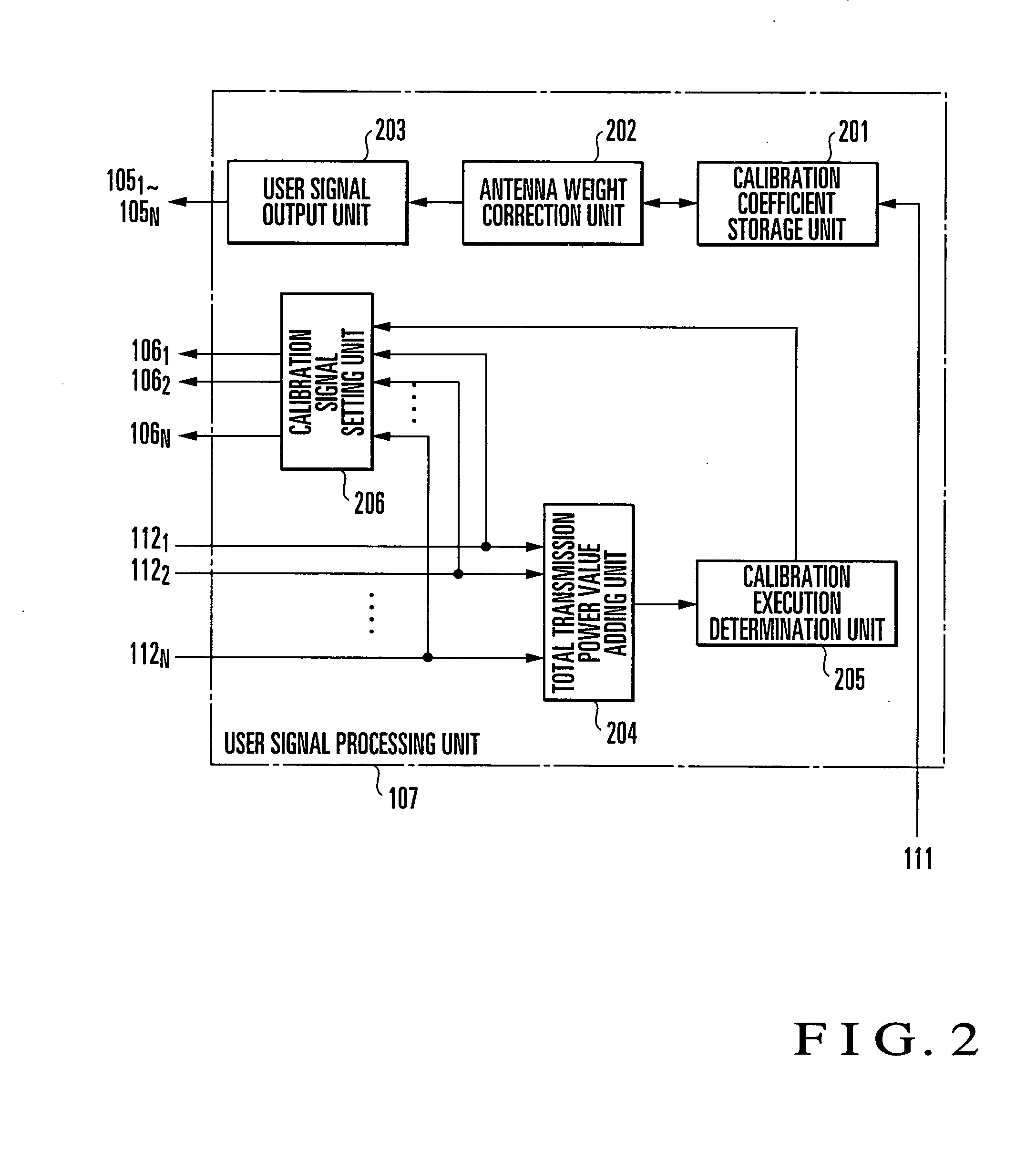
[0075] A modification to the first embodiment will be described next. In the first embodiment, in the user signal processing unit 107, the threshold value for the sum of carrier power utilization ratios is set, and execution of calibration is determined. Instead, execution of calibration may be determined by setting an arbitrary threshold value for the carrier power utilization ratio in each transmission path. The carrier power utilization ratio in each transmission path is obtained by dividing the value of total transmission power in the transmission path, which is output from a corresponding one of the total transmission power measuring unit 11121 to total transmission power measuring unit N 112N by the value of maximum transmission power transmittable from the transmission path. When a threshold value is set for each transmission path, the arrangement can also cope with a system which transmits a control channel from only an arbitrary antenna element.

[0076]FIGS. 3 and 4 show the...

third embodiment

[0082]FIG. 5 shows the arrangement of an array antenna transmitting / receiving apparatus according to the third embodiment of the present invention.

[0083] This array antenna transmitting / receiving apparatus has a function of executing offline calibration. More specifically, the array antenna transmitting / receiving apparatus comprises an array antenna 501 including N antenna elements 5021 to 502N, antenna 1 radio transmitting unit 5041 to antenna N radio transmitting unit 504N, antenna 1 signal processing unit 5051 to antenna N signal processing unit 505N, calibration signal generation unit 15061 to calibration signal generation unit N 506N, user signal processing unit 507, and total transmission power measuring unit 15121 to total transmission power measuring unit N 512N. The transmission path including the antenna 1 radio transmitting unit 5041 will be defined as a transmission path 1. Similarly, the transmission paths including the antenna 2 radio transmitting unit 5042 to antenna...


PUM


Abstract

A transmitting apparatus includes a plurality of antenna elements, user signal output unit, calibration signal generation unit, antenna signal processing unit, and total transmission power measuring unit. The user signal output unit weights a user signal by an antenna weight and outputs it to each antenna element. The calibration signal generation unit outputs a calibration signal to be used to detect the characteristic of a transmission path. The antenna signal processing unit provided in the transmission path executes spread modulation and multiplexing for the user signal and calibration signal and outputs a multiplexed signal. The total transmission power measuring unit measures the value of total transmission power of the multiplexed signal to be transmitted from each antenna element on the basis of the multiplexed signal input from the antenna signal processing unit. An antenna weight correction unit executes a correction operation on the basis of the value of the total transmission power.

Description

BACKGROUND OF THE INVENTION [0001] The present invention relates to a transmitting apparatus using at least two antenna elements, which executes communication while forming a transmission beam by weighting user signal data (code, rate, frequency, or transmission power) transmitted from each antenna element by an antenna weight and, more particularly, to a transmitting apparatus which has a calibration function of correcting an antenna weight in accordance with the characteristic of a transmission path in the apparatus. The user signal data will simply be referred to as a “user signal” hereinafter. [0002] In, e.g., a cellular mobile communication system, a scheme using adaptive antenna control has been examined aiming at an increase in signal speed / quality and subscriber capacity. According to the adaptive antenna control technique, in an array antenna including three or more antenna elements with very high correlation, a transmission beam pattern is formed by controlling at least on...

Claims


Application Information

Patent Timeline
Patent Type & Authority Applications(United States)
IPC IPC(8): H04B1/04H04B7/06H04B7/08H04B7/10H04B17/16H04W16/28H04W24/06H04W52/04
CPCH04B7/0615H04B17/12H04B17/102H04B17/0085
Inventor AZUMA, TOMOHIRO
Owner NEC CORP
Why Eureka
Try Eureka