
Method for providing data associated with the intraoral cavity

a technology of intraoral cavity and data, applied in the field of intraoral cavity, can solve the problems of more difficult stitching procedure, and achieve the effect of significantly better stitching procedur

Active Publication Date: 2005-12-22
ALIGN TECH
View PDF35 Cites 260 Cited by
  • Summary
  • Abstract
  • Description
  • Claims
  • Application Information

AI Technical Summary

Benefits of technology

[0048] By eliminating the data associated with the soft tissues, and proceeding with stitching only the hard tissues using the color data, the quality of the stitching procedure is significantly better than when using the full intra-oral data for the stitching procedure.

Problems solved by technology

However, the data sets often include surface data relating to the soft tissues such as gums, cheeks and tongue, for example, which may distort and move while the different scans are performed.
This relative movement makes the stitching procedure more problematic, since parts of the data sets thus obtained will never synchronise, even though they relate to overlapping portions of the intra-oral cavity.
In U.S. Pat. No. 4,836,674 a method and apparatus are described for obtaining the best color match with respect to adjacent teeth, for different lighting conditions, but considers only the overall color of the teeth, and does not address local variations of color in the teeth.

Method used


Image

  • Method for providing data associated with the intraoral cavity
  • Method for providing data associated with the intraoral cavity
  • Method for providing data associated with the intraoral cavity

Examples


first embodiment

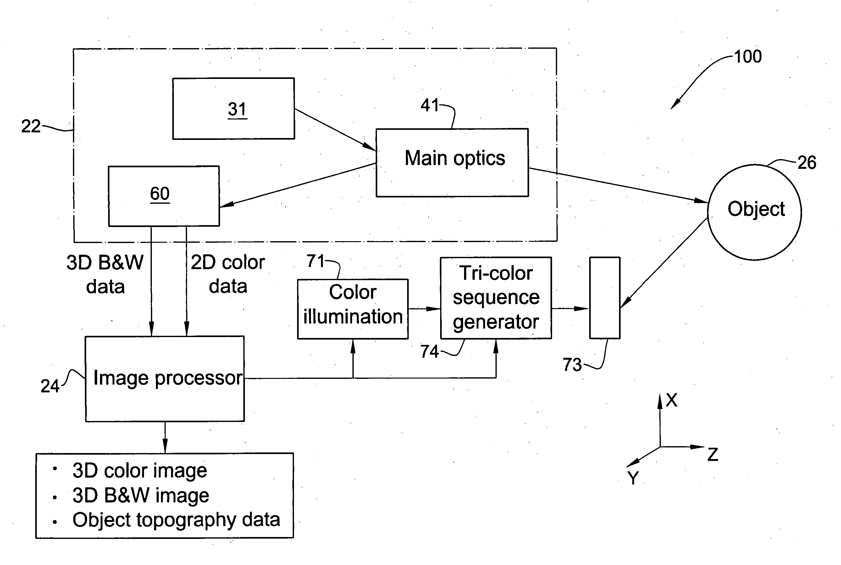
[0124] According to the device 100, the delivery optics 73 is integral with endoscope 46, which is in the form of a probing member 90, as illustrated in FIGS. 5A, 5B and 5C. The probing member 90 is made of a light transmissive material, typically glass and is composed of an anterior segment 91 and a posterior segment 92, tightly glued together in an optically transmissive manner at 93. Slanted face 94 is covered by a totally reflective mirror layer 95. Glass disk 96 defining a sensing surface 97 may be disposed at the bottom in a manner leaving an air gap 98. The disk is fixed in position by a holding structure which is not shown. Three light rays are 99 from the main optics 42 are represented schematically. As can be seen, they bounce at the walls of the probing member at an angle in which the walls are totally reflective and finally bounce on mirror 95 and reflected from there out through the sensing face 97. The light rays focus on focusing plane 101, the position of which can b...

fourth embodiment

[0133] In the device 100, and referring to FIG. 8, tri-color illumination is provided within the main focal optics 42, in particular at the confocal system aperture stop, and facing the objective lens of the system. An advantage provided by this form of illumination is that the tri-color illumination illuminates the object 26 through the downstream objective lens 142 in nearly collimated light, and thus the object illumination is highly uniform. The tri-color light sources 377 may be mounted statically on the physical aperture stop at the aperture stop plane 150, or alternatively they may be mounted on a retracting aperture stop, which also serves to stop down the system aperture in preview mode. In this embodiment, by placing the tri-color light sources 377 at the aperture stop plane, wherein the light beam from the illumination source 31 narrows to a minimum within the main optics 41, the external dimensions of the device 100 may still remain relatively compact.

[0134] Referring to...

seventh embodiment

[0149] According to a second technique for providing the aforesaid 2D color image, the object 26 is illuminated with a white light, and a color CCD is used for receiving the light reflected from the object 26. Thus, the system 100 comprises a white light illumination system 600, illustrated in FIG. 13. The system 600 comprises a while light source 610, such as for example white phosphorus InGaN LED's, and the light therefrom is directed onto a flip mirror 620 via a polarizing beam splitter 650 by means of condenser optics 630. The optical axis OA of the confocal optics 41 is orthogonal to the optical axis OA″ of the light source 610 and condenser optics 630. The mirror 620 is mounted between the aperture stop plane 155 and the objective lens 166 of the confocal optics, and at an angle to the optical axis OA thereof and to the optical axis OA″ of the light source 610 and condenser optics 630.

[0150] The mirror 620 is adapted to flip away from optical axis OA when the device 100 is bei...


PUM


Abstract

A method for providing data useful in procedures associated with the oral cavity, in which at least one numerical entity representative of the three-dimensional surface geometry and color of at least part of the intra-oral cavity is provided and then manipulated to provide desired data therefrom.

Description

FIELD OF THE INVENTION [0001] The present invention relates to color three-dimensional numerical entities representative of tissues, particularly of the intraoral cavity. In particular, the present invention is concerned with the manipulation of such entities to provide data that is useful in procedures associated with the oral cavity, specially dental surfaces thereof. BACKGROUND OF THE INVENTION [0002] There are many procedures associated with the oral cavity in which a precise three-dimensional representation of the cavity is very useful to the dental practitioner. Herein, “practitioner” refers to any one of a dentist, dental surgeon, dental technician, orthodontist, prosthodontist, or any other caregiver that may be involved in determining, preparing or providing dental treatment to a patient, particularly orthodontic treatment. [0003] Such representations enable the practitioner to study the cavity of individual patients in a similar manner to the study of the traditional plast...

Claims


Application Information

Patent Timeline
Patent Type & Authority Applications(United States)
IPC IPC(8): A61B1/04A61B1/24A61B1/247A61B5/00A61B5/05A61B5/107A61C9/00A61C13/00G01B11/24G01J3/02G01J3/50
CPCA61B1/00009H01L27/14868A61B1/0615A61B1/0638A61B1/0676A61B1/0684A61B1/24A61B1/247A61B5/0088A61B5/1077G01B11/24G01J3/02G01J3/0205G01J3/0208G01J3/0216G01J3/0218G01J3/0224G01J3/0243G01J3/0256G01J3/10G01J3/462G01J3/50G01J3/501G01J3/508G01J3/51G06T7/0083G06T7/408G06T2207/10024G06T2207/10028G06T2207/30036H04N13/0207H04N13/0257H04N13/0296A61C9/0066G06T7/0012A61B1/0646A61C9/0053A61C13/0004G01N21/255A61B1/00096A61B5/0068G06T7/12G06T7/90H04N13/15H04N13/207H04N13/257H04N13/271H04N13/296G01B11/25A61B5/1079A61C19/04
Inventor BABAYOFF, NOAM
Owner ALIGN TECH
Learn More