Device for continuous drying of a pulp web

a technology of continuous drying and pulp web, which is applied in the direction of presses, lighting and heating apparatus, furniture, etc., can solve the problems of deformation and even structural damage, and the same damage occurs, and achieve the effects of less specific load, reduced risk of marks on the paper web, and good stability in the cylinder shell

Active Publication Date: 2005-12-29
ANDRITZ AG
View PDF85 Cites 1 Cited by
  • Summary
  • Abstract
  • Description
  • Claims
  • Application Information

AI Technical Summary

Benefits of technology

[0008] It has proved favorable to make the cylinder shell out of longitudinal ribs that are connected to upright, edged profiles. This achieves good stability in the cylinder shell.
[0009] A favorable embodiment of the invention is characterized by the longitudinal ribs of the honeycombed cylinder shell being spaced at a distance of between 20 and 80 mm from one another, preferably between 30 and 40 mm. If the spacing is narrower, there is also less specific load and thus, reduced risk of marks on the paper web.
[0010] An advantageous embodiment of the invention is characterized by the edged connecting profiles mounted in a honeycombed pattern protruding beyond the longitudinal ribs and supporting the paper web and the conveying wire. This results in a large supporting surface and a further reduction in the risk of marks on the paper web.
[0011] It is particularly favorable it the honeycombed cylinder shell has an open area of at least 85%. The through-air drying process can thus be implemented particularly well.
[0012] A particularly favorable further development of the invention is characterized by covers being provided on the face ends to stabilize the cylinder shell and by these covers being bolted to the cylinder shell, particularly to the transition pieces. This design guarantees improved stability of the drum shell; in particular, it prevents any sliding movement by the end cover and the drum shell if there is radial expansion caused by the temperature.
[0013] An advantageous embodiment of the invention is characterized by the drying drum having a fully welded drum body. This design virtually excludes the risk of any areas where cracks could occur.

Problems solved by technology

Due to the substantial differences in mass between drum shell and end flange, there is excessive stress at the transition points that leads to deformation and even structural damage.
The same damage occurs if the drums are cooled down abruptly from operating to ambient temperature during an emergency shutdown, when they are sprayed with cold water in order to prevent the plastic wires enclosing the drums from being damaged.

Method used


Image

  • Device for continuous drying of a pulp web
  • Device for continuous drying of a pulp web
  • Device for continuous drying of a pulp web

Examples


Embodiment Construction

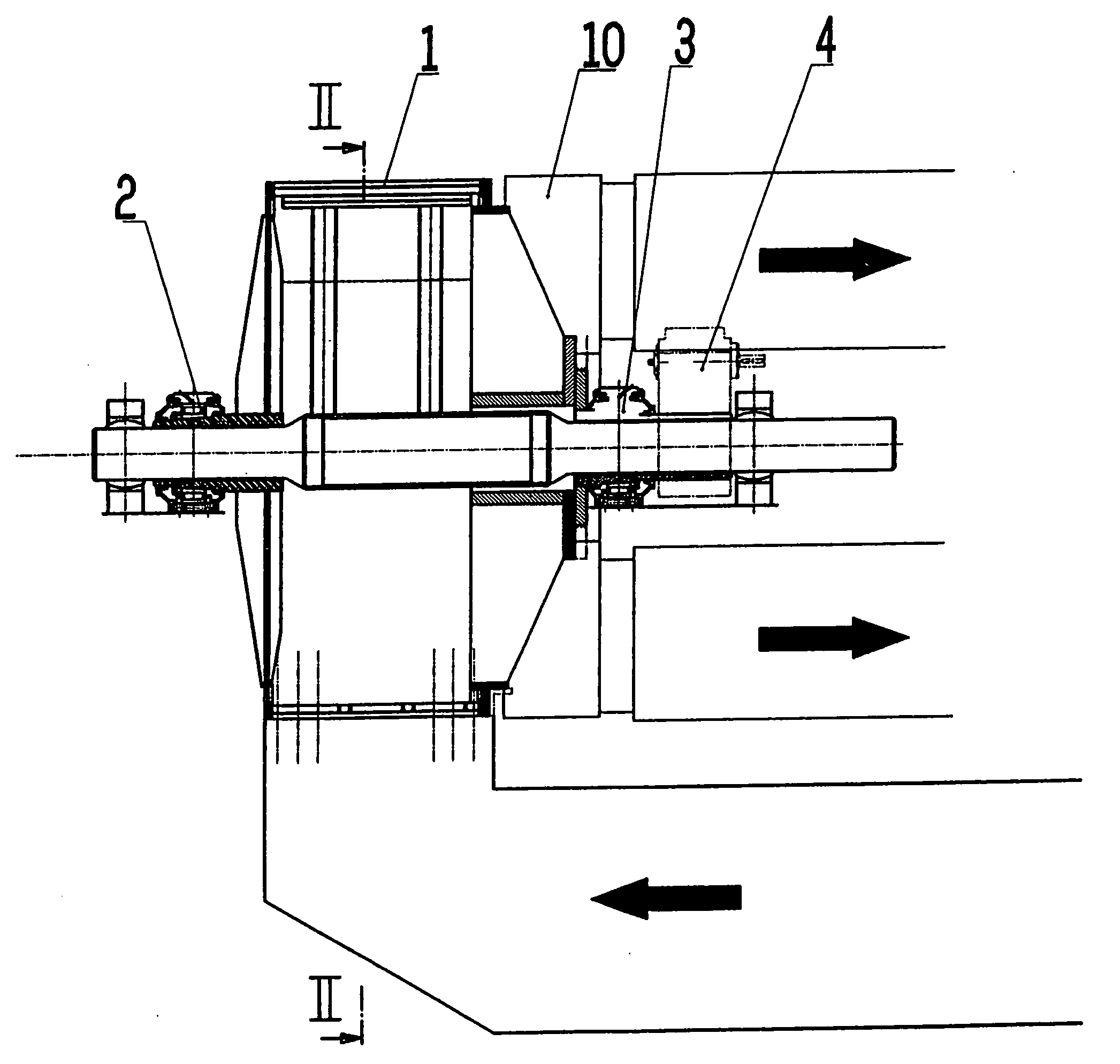
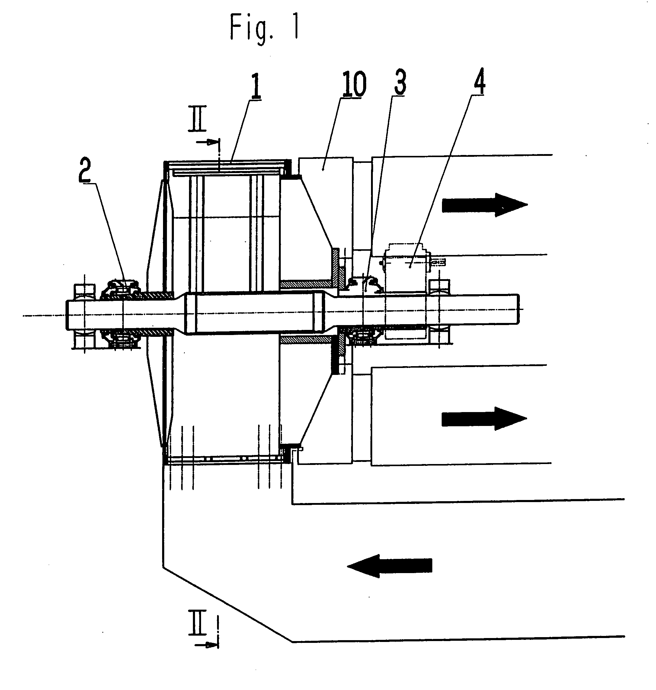
[0021]FIG. 1 shows a possible configuration of a through-air drying process. The figure shows the drum 1 with its bearings 2 and 3, and the drive 4.

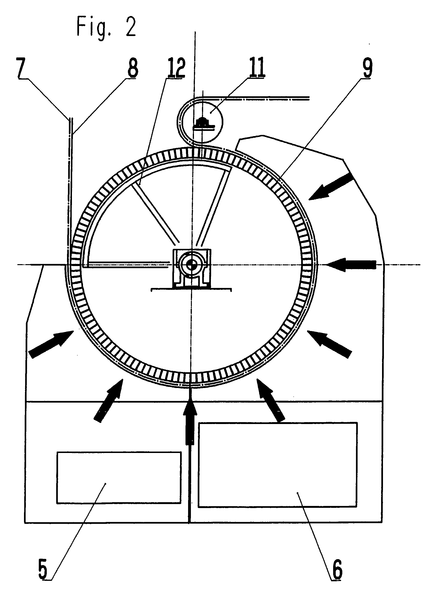
[0022] Beneath the drum there is a two-part hood 5 and 6 (see FIG. 2) from which the hot supply air flows through the paper web, through a conveying wire 8, then through the drying drum 1 into the inside of the drum, and is removed from the drum on the drive side through an annular channel 10. The hot supply air at a temperature of approximately 300° C. is cooled down to approximately 120° C. by the drying process. The exhaust air cooled in this way is then returned to its entry status in a processing system. At the outlet, the paper web 7 with the conveying wire 8 is carried over a deflection roll 11. The cover device 12 is clearly visible here, covering the area of the drum 1 from the inside outwards in the sector that does not come into contact with the tissue web 7 and which also is not enclosed by the hood 5 and 6. This prevents ad...


PUM


Abstract

A device for continuous drying of a pulp web, particularly a tissue web, with a drying drum (1) and an air circulating system, where the drying drum (1) has a cylindrical shell (9) designed as a honeycombed body with an annular, flexible transition profile (13) at the edges of the shell and connected to the end covers.

Description

BACKGROUND OF THE INVENTION [0001] The invention relates to a device for continuous drying of a pulp web, particularly a tissue web, with a drying drum and an air circulating system, where the drying drum has a cylindrical shell designed as a honeycombed body. [0002] In conventional tissue plants, the drying process begins at an ingoing dryness of some 40 to 45%. In order to achieve higher paper volume, papermakers now dispense with preliminary mechanical dewatering, and the ingoing dryness of this newer type of device is around 20 to 25%. These plants operate with through-air drying. During the heating process, one or more consecutive through-air drying drums at ambient temperature are exposed abruptly to the supply air temperature of approximately 300° C. The drying drums currently in use have a thin-walled shell, for example a perforated or honeycombed body, that is joined to thick-walled end flanges. Due to the substantial differences in mass between drum shell and end flange, t...

Claims


Application Information

Patent Timeline
Patent Type & Authority Applications(United States)
IPC IPC(8): D21F5/02D21F5/18F26B3/00F26B11/02
CPCD21F5/021
Inventor MAUSSER, WILHELMSCHADLER, GERALD
Owner ANDRITZ AG
Why Eureka
Try Eureka