Stamper, imprinting method, and method of manufacturing an information recording medium

a technology of information recording medium and imprinting method, which is applied in the direction of manufacturing tools, photomechanical equipment, instruments, etc., can solve the problems of difficult to make the width of concave parts, difficult to press the positions where features are placed, and resin layer, so as to avoid corrosion of the side surfaces

Inactive Publication Date: 2005-12-29
TDK CORPARATION
View PDF6 Cites 21 Cited by
  • Summary
  • Abstract
  • Description
  • Claims
  • Application Information

AI Technical Summary

Benefits of technology

[0014] According to this stamper, imprinting method, and method of manufacturing an information recording medium, a concave/convex pattern is formed so that the respective convex parts are formed so that a distance between a top of a convex part and a reference plane (as one example, a base surface of any of the concave parts in the concave/convex pattern) is longer for convex parts with wide widths than for convex parts with narrow widths. This means that when a uniform pressing force is applied across the entire stamper during imprinting, it is possible to press the wide convex parts sufficiently deeply into the resin layer. Since it is possible to press both wide convex parts and narrow convex parts substantially uniformly and sufficiently into the resin layer, the thickness of the residue on the substrate can be made uniform across the entire region. Accordingly, since the time required to remove the residue is substantially equal across the entire region, it is possible to avoid corrosion of the side walls of the concave parts of the concave/convex pattern which would result in the widths of the concave parts changing to unintended widths. By doing so, it is possible to precisely form a concave/convex pattern with the correct pattern widths across the entire region. Also, by manufacturing an information recording medium using the concave/convex pattern that has the correct pattern widths, it becomes possible to manufacture an information recor

Problems solved by technology

However, with the conventional imprinting method, since the concave/convex pattern is pressed into the resin layer with a substantially uniform pressing force across the entire stamper, it is difficult to sufficiently press the positions where the features with the comparatively wide widths are formed into th

Method used


Image

  • Stamper, imprinting method, and method of manufacturing an information recording medium
  • Stamper, imprinting method, and method of manufacturing an information recording medium
  • Stamper, imprinting method, and method of manufacturing an information recording medium

Examples


Embodiment Construction

[0040] Preferred embodiments of a stamper, an imprinting method, and a method of manufacturing an information recording medium will now be described with reference to the attached drawings.

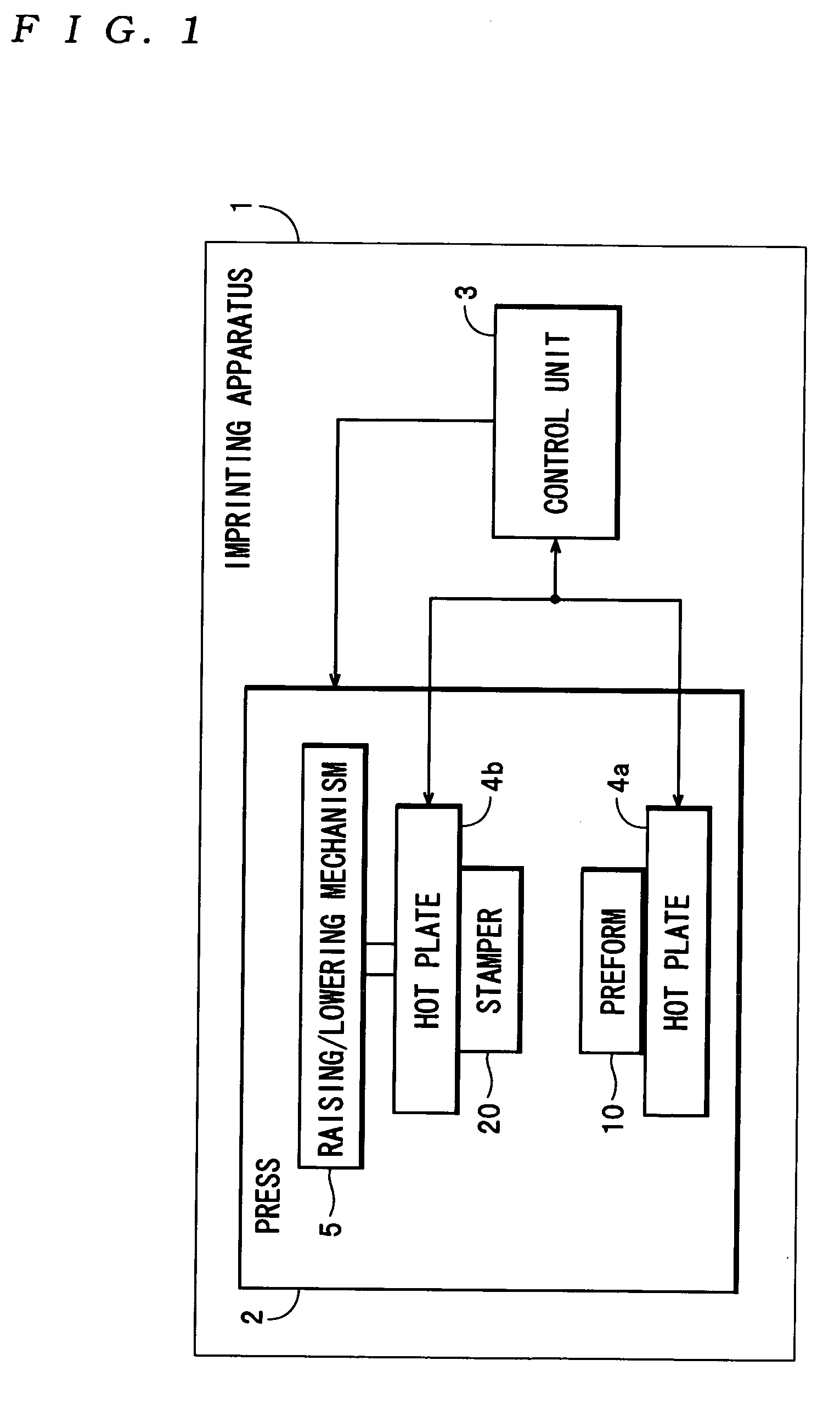
[0041] First, the construction of an imprinting apparatus 1 that manufactures an information recording medium using a stamper according to the present invention will now be described with reference to the attached drawings.

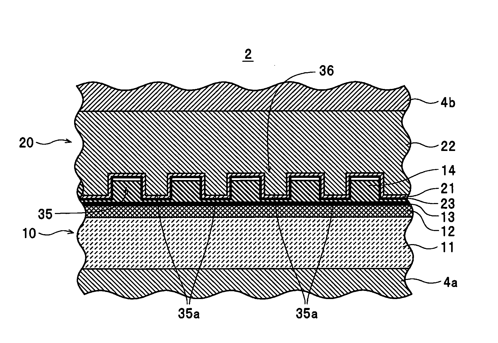
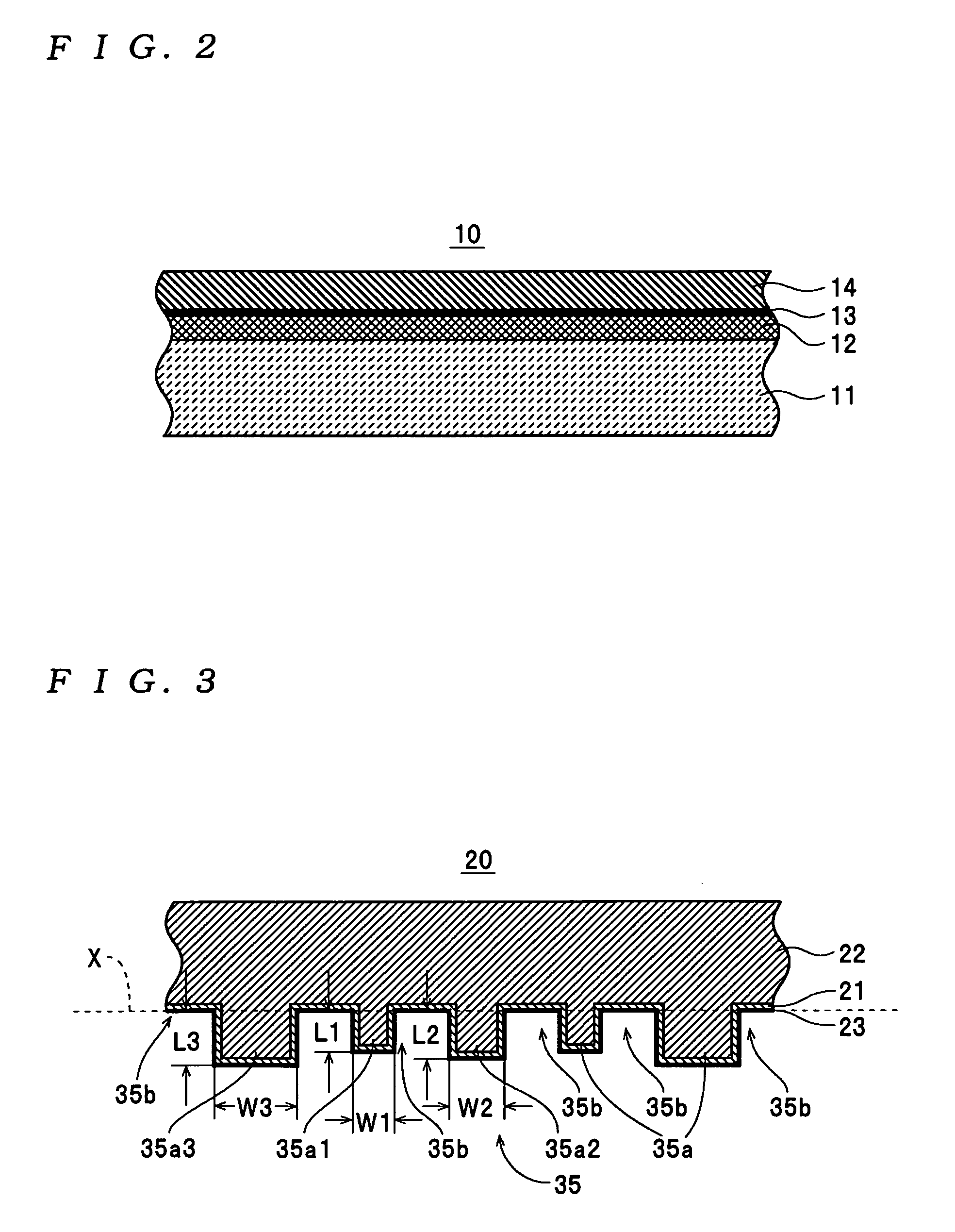
[0042] The imprinting apparatus 1 shown in FIG. 1 is a device that presses a stamper 20 (see FIG. 3) onto a preform 10 (see FIG. 2) using an imprinting method according to the present invention to form a concave / convex pattern 36 (see FIG. 17) when manufacturing an information recording medium 40 shown in FIG. 19, and includes a press 2 and a control unit 3. In this example, the information recording medium 40 is a discrete track magnetic recording medium on which a concave / convex pattern 38 is formed as shown in FIG. 19. The concave / convex pattern 38 is composed of a large nu...


PUM

PropertyMeasurementUnit
Widthaaaaaaaaaa
Widthaaaaaaaaaa
Distanceaaaaaaaaaa

Abstract

There is provided a stamper for imprinting on which a concave/convex pattern is formed with a plurality of convex parts of different widths protruding from a surface. In the concave/convex pattern, the respective convex parts are formed so that a distance between a top of a convex part and a reference plane defined in a range between the surface and a rear surface of the stamper is longer for convex parts with wide widths than for convex parts with narrow widths. An imprinting method transfers the concave/convex form of the stamper to a resin layer on the surface of a substrate. A method of manufacturing an information recording medium uses the concave/convex form transferred by the imprinting method to manufacture an information recording medium.

Description

BACKGROUND OF THE INVENTION [0001] 1. Field of the Invention [0002] The present invention relates to a stamper for imprinting that is used when manufacturing an information recording medium or the like, an imprinting method that presses a stamper onto a resin layer formed on the surface of a substrate to transfer a concave / convex pattern of the stamper, and a method of manufacturing an information recording medium that manufactures an information recording medium using the concave / convex pattern transferred to the resin layer. [0003] 2. Description of the Related Art [0004] Optical lithography is conventionally known as a method of forming a fine concave / convex pattern (a resist pattern) in a resist layer formed on the surface of a substrate as part of a process that manufactures a semiconductor element, an information recording medium, or the like. During optical lithography, light for exposing the resist layer formed on the substrate is irradiated to form an exposure pattern and t...

Claims


Application Information

Patent Timeline
IPC IPC(8): B28B11/08B29C59/00B30B12/00B44C1/22B81C99/00G03F7/00G11B7/24079G11B7/24091G11B7/26
CPCB82Y10/00G11B5/855G03F7/0002B82Y40/00
Inventor HATTORI, KAZUHIROFUJITA, MINORUOKAWA, SHUICHI
Owner TDK CORPARATION
Why Eureka
Try Eureka