Image conversion device

a conversion device and image technology, applied in the direction of color signal processing circuits, television systems, television system scanning details, etc., can solve the problems of a single frame delay, a maximum of approximately 2 frames, and a prior art approach that is complex, so as to shorten the delay in displaying the detected image and reduce the memory volume

Inactive Publication Date: 2005-12-29
NISSAN MOTOR CO LTD
View PDF4 Cites 16 Cited by
  • Summary
  • Abstract
  • Description
  • Claims
  • Application Information

AI Technical Summary

Benefits of technology

[0014] The present invention was developed in light of the previously described circumstances and its purpose is to offer a vehicle...

Problems solved by technology

The inventors recognized that this prior art approach is complex, because the configuration for the controller needs to create a synchronizing signal and provide a signal line for supplying the synchronizing signal to each camera.
However, with the technology described above, because the image signal input from each camera is processed in single frame units, a delay of a maximum of approximately 2 frames occurs in order to obtain synchronization between respective image signals in the input buffer.
Additionally, if address conversion processing is performed and the timing for displaying an image is synchronized with the timing stored of images from all cameras in the output side of the input buffer, a delay of a single frame occurs.
While some delay can be permissible when using a vehicle surroundings image conversion device in lower speed ranges, such as parking and inching closer to another vehicle, it is unacceptable when using it when entering...

Method used


Image

  • Image conversion device
  • Image conversion device
  • Image conversion device

Examples


Embodiment Construction

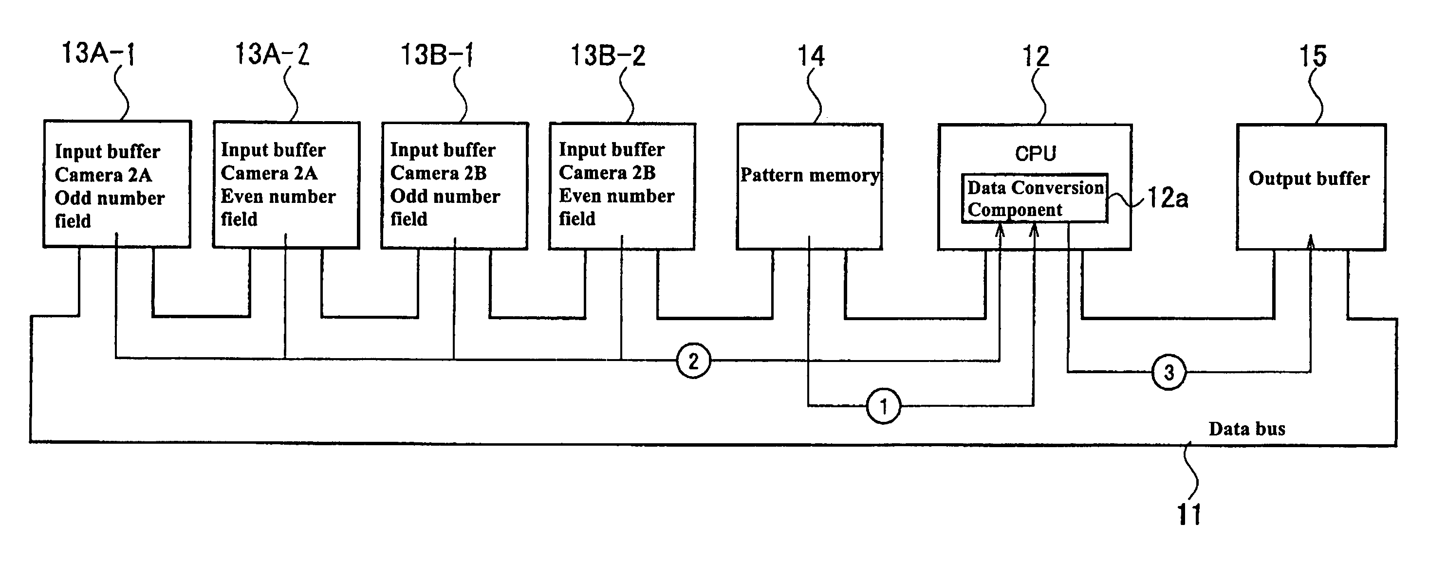
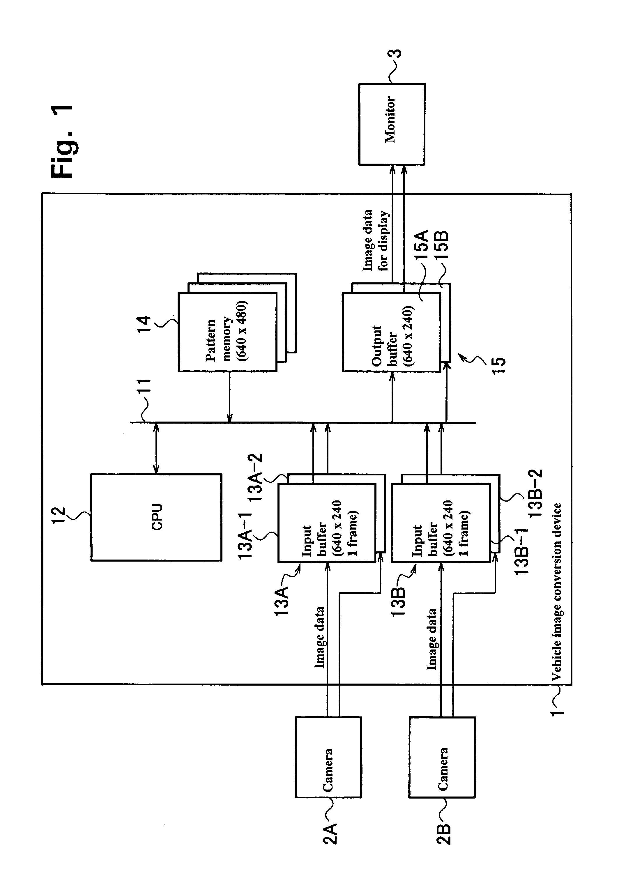
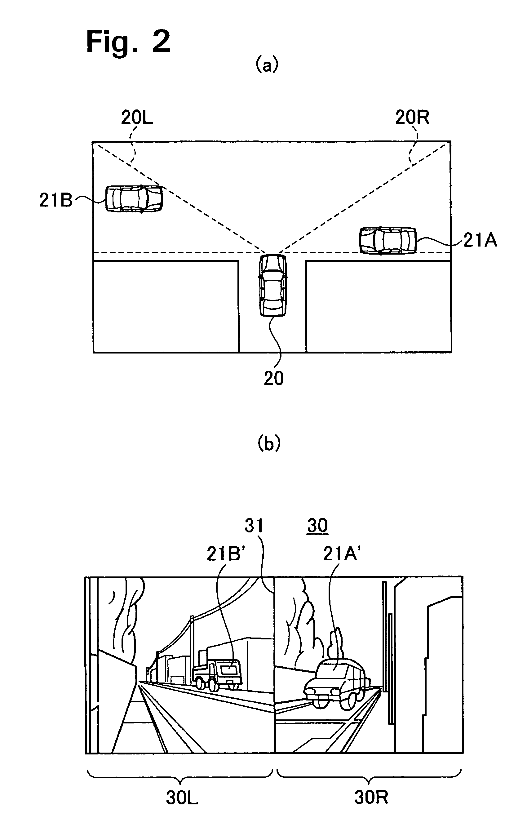
[0027] The present invention is applicable for a vehicle surroundings image conversion device 1 for a driving support system configured as shown in FIG. 1, for example. A driving support system furnished with vehicle surroundings image conversion device 1 allows a vehicle 20 entering a T-shaped intersection to display an area that is a blind angle to the driver of that vehicle. FIG. 2(a) shows an example where the vehicle and other vehicles are at a T-shaped intersection with poor visibility. The device 1 captures an image of right side direction imaging sector 20R with NTSC camera 2A and captures an image of left side direction imaging sector 20L with NTSC camera 2B, by virtue of image conversion processing which will be discussed later. The device causes left and right side directions image 30, which is a so-called blind-corner view, to be displayed on display monitor 3 and is arranged on the screen as shown in FIG. 2(b), dividing right side direction image 30R which contains othe...


PUM


Abstract

An image conversion device connected to multiple image detection mechanisms generating field image data of the surroundings and having multiple input buffers for each of the multiple image detection mechanisms, which, in parallel, stores, moves, performs conversion processing and displays said field image data in 1 field units in accordance with a display template in pattern memory, thereby reducing the total delay time from field image generation to display to the driver.

Description

[0001] This application claims the benefit of Japanese Application No. 2004-169918, filed Jun. 8, 2004, the entirety of which is incorporated herein by reference. FIELD OF THE INVENTION [0002] The present invention relates to an image conversion device which performs address conversion processing for multiple images in order to present these multiple images on a display. BACKGROUND OF THE INVENTION [0003] Vehicle surroundings image conversion devices have been used in driver support systems for assisting and aiding the vision of a driver in situations when a driver is backing a vehicle (such as parking in a garage or inching close to another vehicle) or driving forward and entering an intersection where visibility is poor or a T-shaped intersection. [0004] The places imaged by the camera connected to such a vehicle surroundings image conversion device are, for example, behind the vehicle for the purpose of displaying a rear view, and the left and right directions from the front of t...

Claims


Application Information

Patent Timeline
IPC IPC(8): H04N5/265H04N7/18
CPCH04N7/181
Inventor SUZUKI, MASAYASUAKATSUKA, TAKESHI
Owner NISSAN MOTOR CO LTD
Why Eureka
Try Eureka