Scanning ophthalmic fixation method and apparatus
a technology of ophthalmoscope and fixation method, which is applied in the field of scanning ophthalmoscope fixation method and apparatus, can solve the problems of patients' discomfort, discrete points of light, and static fixation device approaches, and achieves the effects of reducing patient discomfort, avoiding patient discomfort, and avoiding ophthalmoscope ophthalmology
- Summary
- Abstract
- Description
- Claims
- Application Information
AI Technical Summary
Benefits of technology
Problems solved by technology
Method used
Image
Examples
second embodiment
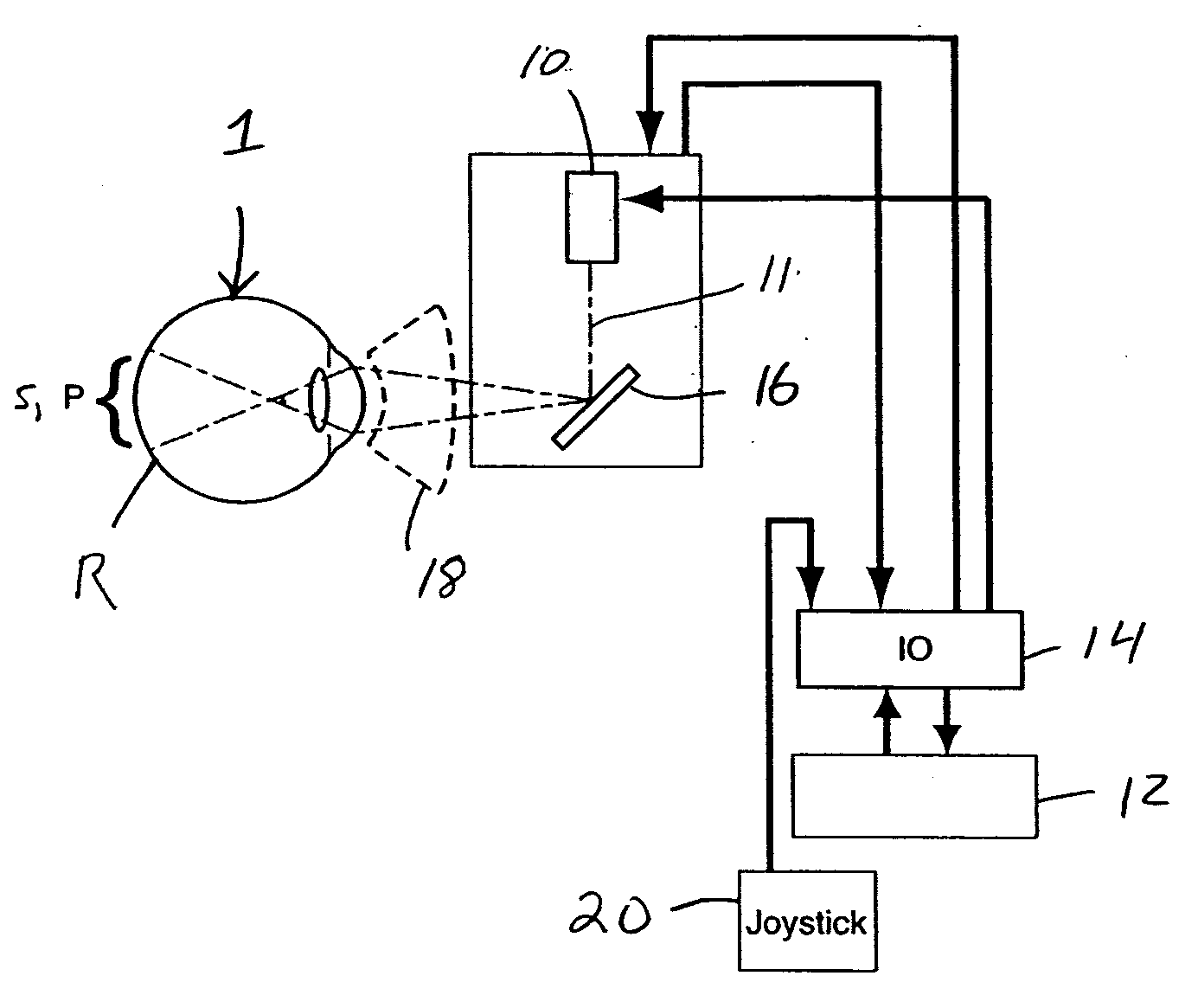
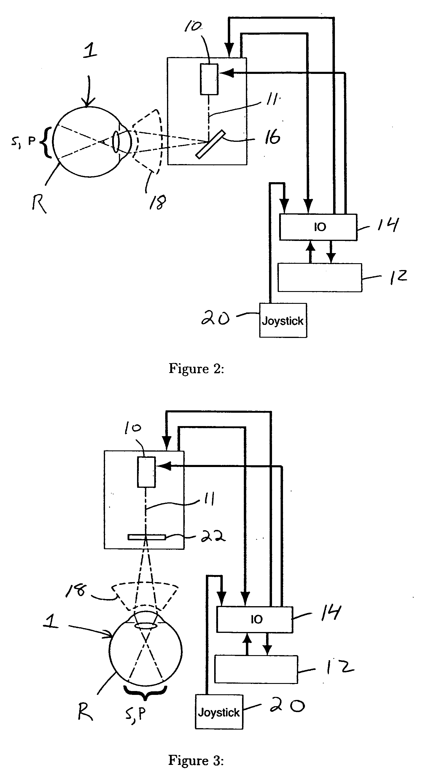
[0047]FIG. 9 shows a schematic diagram of the present invention, which is similar to that discussed with respect to FIGS. 2 and 3, but with the addition of another scanning element. In this embodiment, scanning is achieved by using a pair of orthogonal optical elements 24 and 26, each able to move or deflect the optical beam 11 in one of two orthogonal directions. Optical elements 24 / 26 could be any combination of mirrors, lenses, diffractive elements etc. that can be used to move / deflect the beam 11. Optical elements 24 / 26 may be mounted upon, for example, galvanometers, solenoids, piezoelectric actuators, motors, etc. that move or tilt the optical elements 24 / 26, which in turns moves / deflects the beam 11. In this embodiment, beam 11 would include light for both S and P patterns, preferably temporally interleaved, so that a single scanning system (i.e. optical elements 24 / 26) can be used to generate both fixation and procedure patterns P and S.
[0048]FIG. 10 shows a schematic diagra...
sixth embodiment
[0051]FIG. 13 shows a schematic diagram of a sixth embodiment which is similar to that discussed with respect to FIG. 11, but additionally includes aiming light, beam shuttering, and power measurements, such as may be found in a commercial photo-medical device. In this embodiment, light output from source 10 first encounters mirror 54 which directs a portion of the light to a sensor 56 (e.g. photodiode) which serves to sample and measure the power of the light for safety purposes. Following that, the light then encounters shutter 58, mirror 60, and mirror 62. Shutter 58 fundamentally serves to control the delivery of the light beam 11 (e.g. used to gate the light, in addition to grossly blocking it). Mirror 60 is shown as a turning mirror, where it might also be used in conjunction with mirror 62 to align the light beam 11 into fiber optic 42. Mirror 62 is shown as a combining mirror for combining aiming light from aiming light source 48, and for directing the combined light into fi...
seventh embodiment
[0052]FIG. 14 shows a schematic diagram of the present invention which is similar to that described above with respect to FIG. 13, but with the addition of a separate light source 52. In this embodiment, light source 10 provides the light for pattern P, and light source 52 provides the light for pattern S. In this embodiment, mirror 66 is a dichroic mirror used to combine the P and S pattern light together. All three lights sources can be controlled by the host system's control electronics 12 via input and output device 14.
[0053]FIG. 15 shows a timing diagram of one of many possible schemes for temporally interleaving patterns P and S in any of the above embodiments. The number, permutation, and duration of the individual scan elements may vary to suit the particular clinical need. By interleaving the timing of P and S light patterns, these patterns can be individually and independently imaged onto the eye using the same scanning optical elements, which minimizes the number and comp...
PUM
 Abstract
Description
Claims
Application Information
 - R&D
- Intellectual Property
- Life Sciences
- Materials
- Tech Scout
- Unparalleled Data Quality
- Higher Quality Content
- 60% Fewer Hallucinations
Browse by: Latest US Patents, China's latest patents, Technical Efficacy Thesaurus, Application Domain, Technology Topic, Popular Technical Reports.
© 2025 PatSnap. All rights reserved.Legal|Privacy policy|Modern Slavery Act Transparency Statement|Sitemap|About US| Contact US: help@patsnap.com


