
Ammonia synthesis process and apparatus for use therein

Inactive Publication Date: 2005-12-29
AMMONIA CASALE SA
View PDF5 Cites 3 Cited by
  • Summary
  • Abstract
  • Description
  • Claims
  • Application Information

AI Technical Summary

Benefits of technology

[0011] The problem at the base of the present invention is that of providing a method for synthesis ammonia production of the type considered above, in which the purification system of the synthesis gas has functional characteristics so as to overcome the drawbacks quoted above with reference to the prior art and in particular so as to allow a substantial energy saving compared to the methods used up to now.

Problems solved by technology

But besides the substantial operating costs the chilling unit and the recondensation of the ammonia vaporised there, the aforementioned methods involve increased costs for the necessary subsequent step of heating the purified gas to the predetermined temperature of entry into the reactor.
To reduce if not actually avoid such a dissipation of energy, in the most common purification systems, units based upon the use of molecular screens have been used; however, compared to a recognisedly high efficiency, said systems still involve very high operating and investment costs.
Although advantageous for some aspects, the purification method according to the prior art has different recognised technical drawbacks Firstly, the synthesis gas crossing the washing column for its purification undergoes a predetermined pressure drop.
This pressure drop must be necessarily recovered downstream of such washing with the consequent energy consumptions of the compressor.
Moreover, this type of purification causes an appreciable evaporation of the liquid washing ammonia that is thus absorbed by the flow of synthesis gas and thus inevitably recycled in the reactor at the expense of the conversion yield thereof.
A reduction in the conversion yield of the reactor has, moreover, as a consequence, an increase in the amount of unreacted substances that have to be separated from the flow of ammonia produced and to be recycled to the reactor, with consequent overloads at the sections intended for such operations and high energy consumptions.

Method used


Image

  • Ammonia synthesis process and apparatus for use therein
  • Ammonia synthesis process and apparatus for use therein

Examples


Embodiment Construction

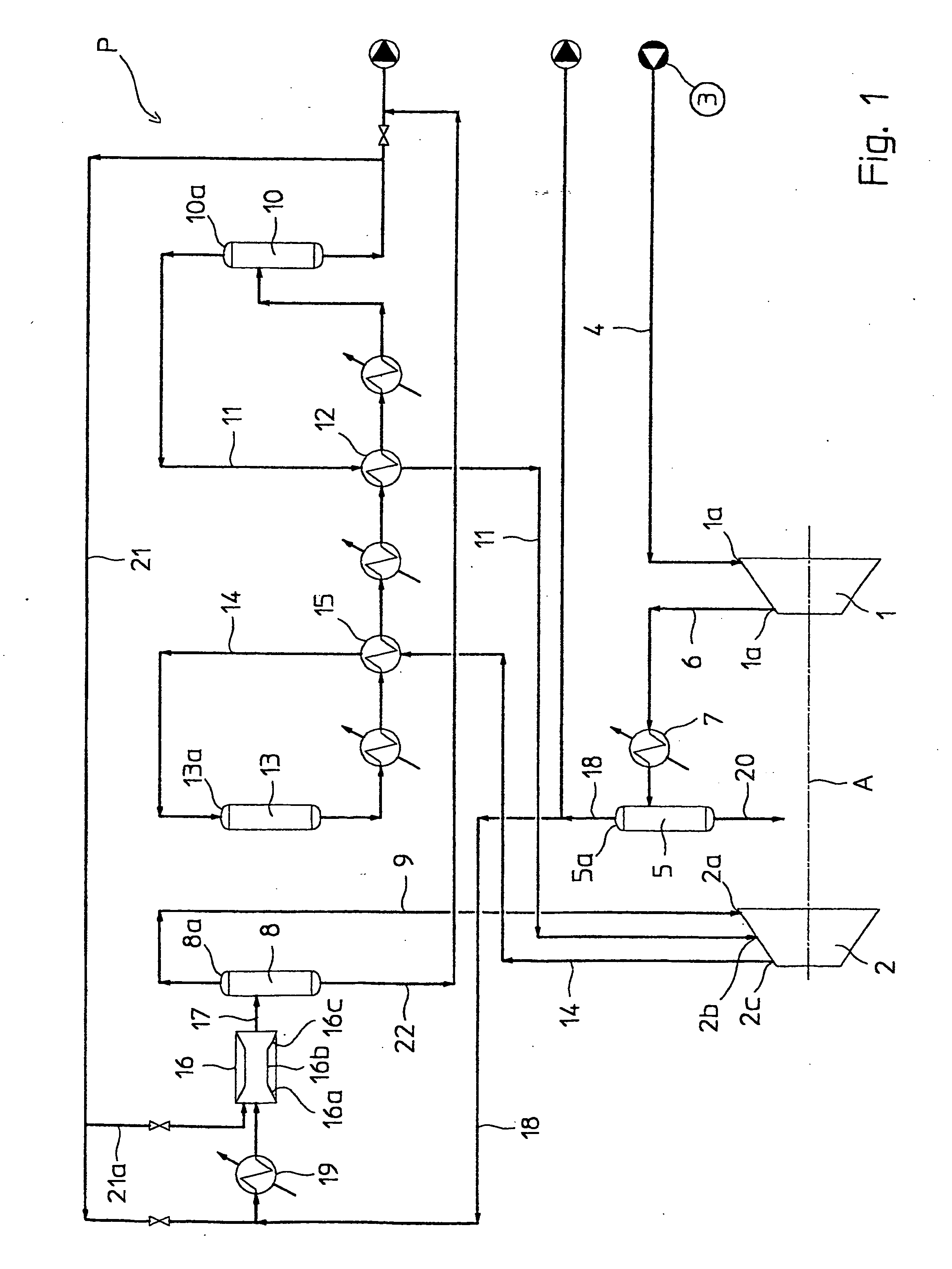
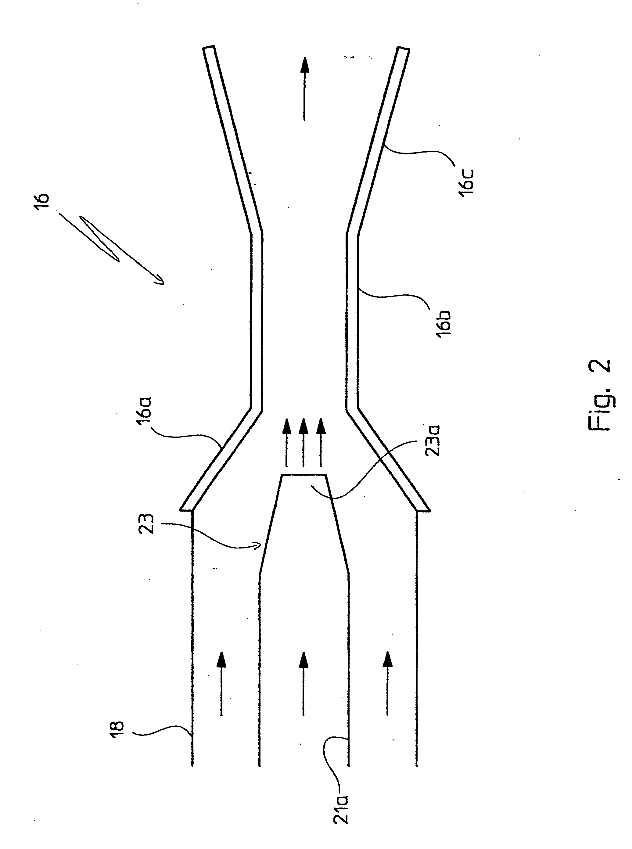
[0020] With reference to the figures, a plant for the production of ammonia is globally schematically indicated with P, comprising an apparatus for carrying out the method of the present invention, which comprises a compressor with many stages, of which just the longitudinal axis A is shown, and where with 1 and 2 two subsequent stages thereof are schematically indicated, aligned and adjacent on said axis A. Preferably, but not for limiting purposes, such a compressor is a two stage compressor, of which one is for what is known as make-up gas compression and a final stage for what is known as recycling compression.

[0021] The stage 1 has an inlet 1a (or suction end) in fluid communication with a source 3 of synthesis gas through a line 4 and has an outlet 1b (or discharge end) in fluid communication with a first gas-liquid separator 5, through a line 6 and a cooling group 7.

[0022] The stage 2 has a first inlet 2a in fluid communication with the head 8a of a second gas-liquid separa...


PUM

PropertyMeasurementUnit
Temperatureaaaaaaaaaa
Angleaaaaaaaaaa
Flow rateaaaaaaaaaa

Abstract

Method for ammonia production through a catalytic reaction of pressurised synthesis gas in an appropriate compressor with many stages (1, 2), each of which is equipped with an inlet and outlet (1a, 2a, 1b, 2b) for said synthesis gas said method including a purification step through liquid ammonia of said synthesis gas from water and carbon dioxide contained in it.

Description

FIELD OF APPLICATION [0001] The present invention refers, in its most general aspect, to a method and relative apparatus for ammonia production through a catalytic reaction of synthesis gas, comprising hydrogen and nitrogen, previously pressurised in a suitable compressor with two or more stages. [0002] In particular this invention concerns a method of the aforementioned type in which a purification step of the synthesis gas is provided for through separation of water and carbon dioxide contained therein, carried out in correspondence with an intermediate stage of said compressor. [0003] More specifically, the present invention refers to a method of the considered type, in which the synthesis gas is collected when exiting from a predetermined stage of said compressor, is purified and cooled at a predetermined temperature, through washing with substantially anhydrous liquid ammonia, and then is fed again into a stage of said compressor, after the one from which it was collected. PRIO...

Claims


Application Information

Patent Timeline
IPC IPC(8): B01F3/04B01F5/04C01B3/02C01B3/52C01C1/04
CPCB01F3/04099B01F5/0413B01F5/0428C01B3/025C01C1/0405C01B2203/0415C01B2203/0475C01B2203/0495C01B3/52Y02P20/52B01F23/23B01F25/31242B01F25/312
Inventor DEBERNARDI, SERGIO
Owner AMMONIA CASALE SA
Learn More