
Method and apparatus for capturing target substance

a target substance and target substance technology, applied in the field of target substance capture methods, can solve the problems of permeability and reactivity of the porous body, flow resistance, and it is not easy to efficiently wash the entire porous body, and achieve the effects of improving the efficiency of the capture reaction, increasing the apparent surface area of the reaction site, and reducing the diffusion length of the target substan

Inactive Publication Date: 2005-12-29
CANON KK
View PDF4 Cites 24 Cited by
  • Summary
  • Abstract
  • Description
  • Claims
  • Application Information

AI Technical Summary

Benefits of technology

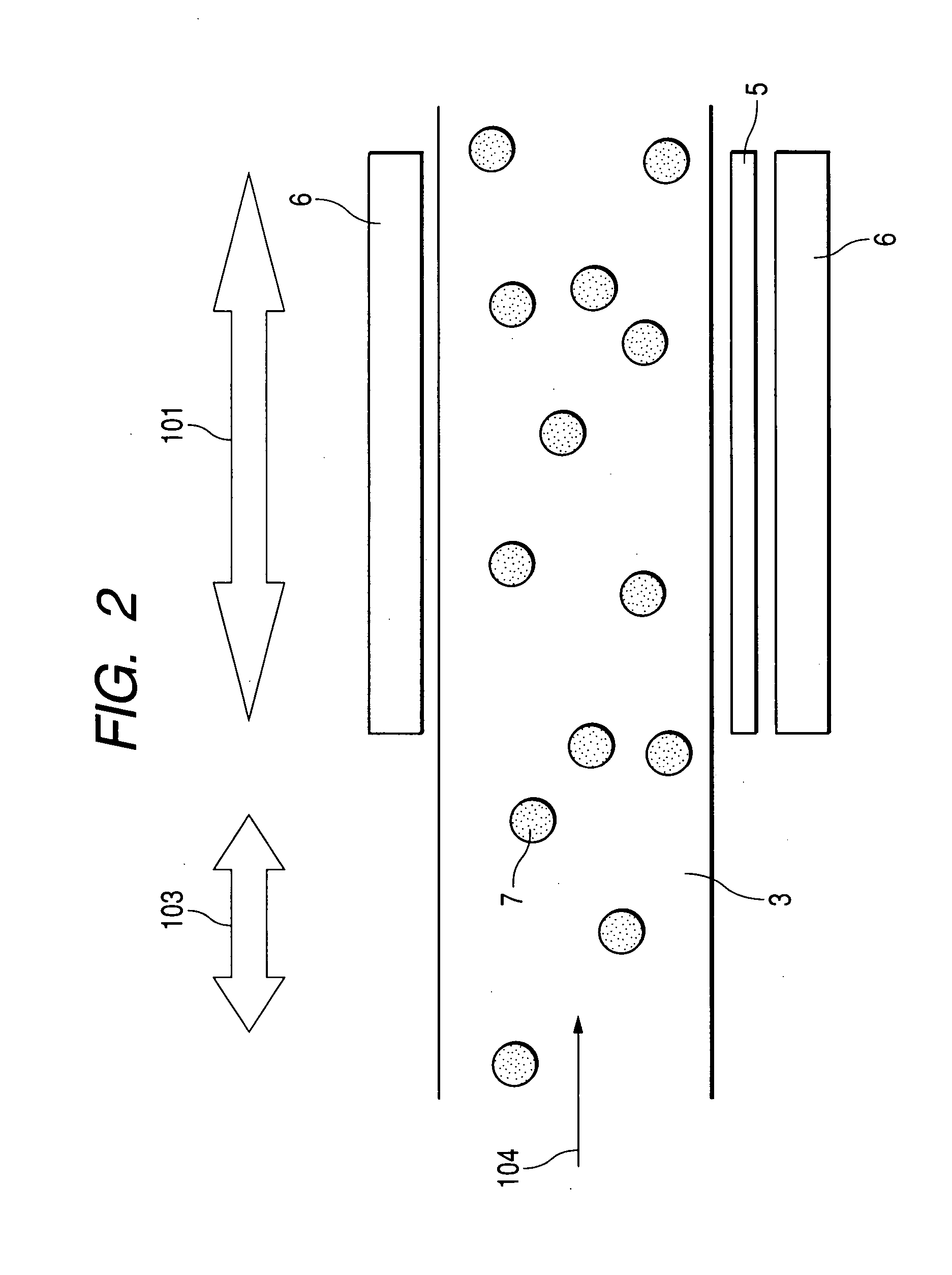
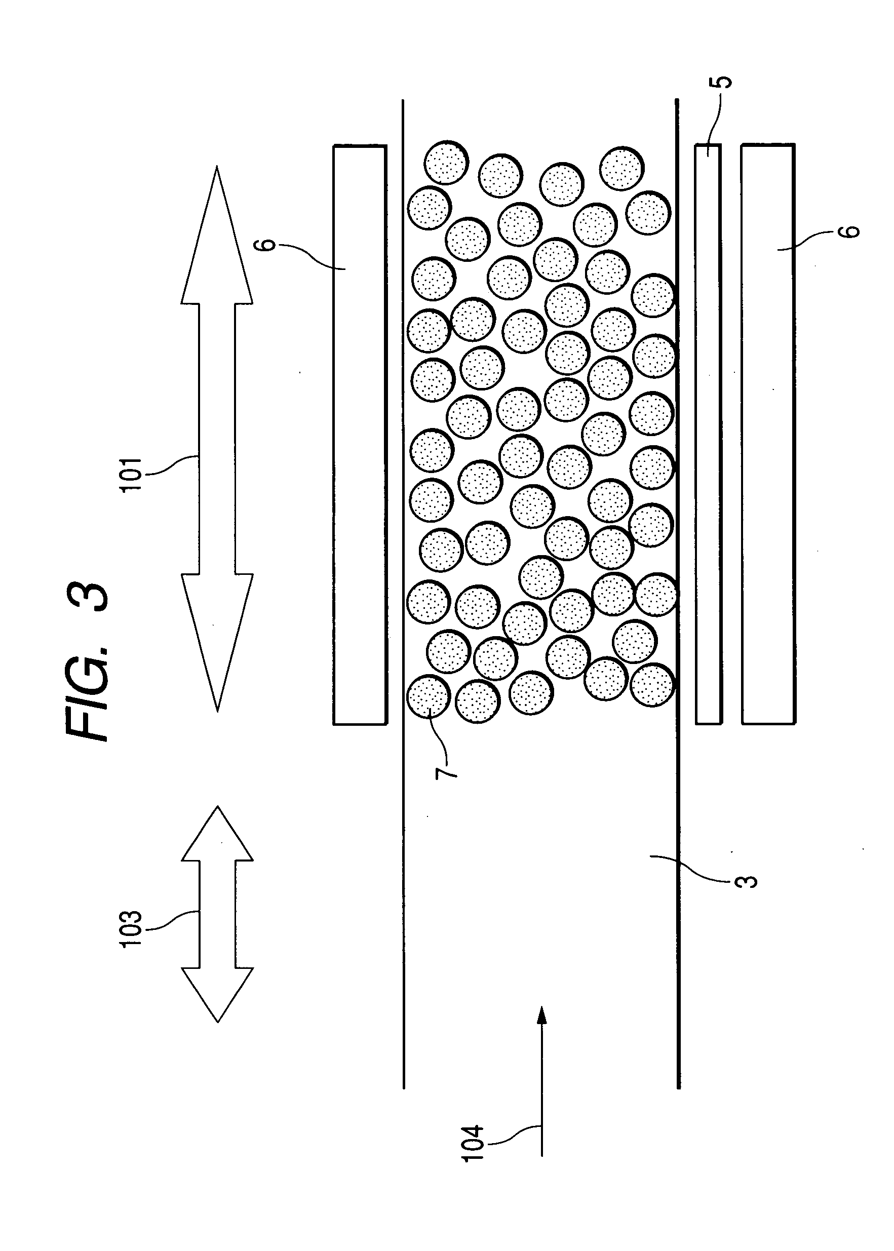
[0006] The present invention has been made in view of the background art and provides a method and apparatus for capturing a target substance improved in efficiency of a capturing reaction by forming a porous body which consists of a particle aggregate capable of capturing the target substance through a reaction, thereby increasing an apparent surface area of a reaction site, and reducing the diffusion length of the target substance. The present invention also employs particles capable of producing a reversible aggregate. Therefore, after the reaction between a particle aggregate and a sample, the particle aggregate can be redispersed, so that the redispersed particles can be subjected to other steps such as detecting and collecting a captured target substance.

Problems solved by technology

However, when the surface area of a porous body is increased to detect a trace of constituents selectively or to increase the sensitivity, it is usually not easy to wash efficiently the entire porous body during a washing step carried out after a capturing reaction.
Such a porous body has problems in permeability and reactivity when used in a solution system, and in flow resistance when used in a microchannel.

Method used


Image

  • Method and apparatus for capturing target substance
  • Method and apparatus for capturing target substance
  • Method and apparatus for capturing target substance

Examples


example 1

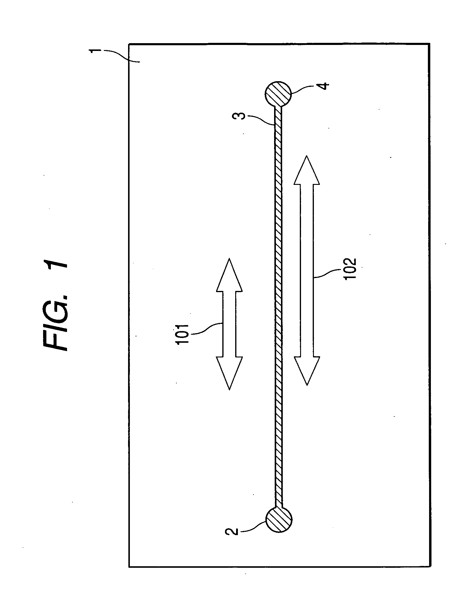
[0039]FIG. 5 is a schematic view for illustrating a method for capturing a target substance according to Example 1 of the present invention. The target substance capturing apparatus of FIG. 5 is formed of a base (substrate) 1, a flow channel 3, an inlet 2 for introducing a deliver solution containing fine particles and a target substance into the flow channel 3, and an outlet 4 for discharging the deliver solution (from which the fine particles and the target substance have been delivered) from the flow channel 3. Between the inlet 2 and the outlet 4, a plurality of fine particle aggregation regions 101A, 101B and detection regions 102A, 102B are arranged.

[0040] The capturing apparatus of FIG. 5 employs a composite substrate 1, which is formed by adhering a polydimethyl siloxane (PDMS) resin substrate and a glass substrate to each other. The flow channel 3 of 100 μm width and 50 μm depth is formed by removing a predetermined portion from the PDMS substrate by a molding method using...

example 2

[0045] In the same manner as in Example 1, a target substance is specifically captured in a fine particle aggregation section in a flow channel. This Example is directed to removing viruses contained in a target solution. An antibody specifically binding to adenovirus is immobilized on the surface of fine magnetic particles. Adenovirus is captured by the resultant fine magnetic particles in fine particle aggregation region, thereby removing adenovirus from the target solution. The fine magnetic particles capturing adenovirus are redispersed by removing a magnetic field from the aggregation region while supplying a phosphate buffer from the inlet 2, simultaneously. In this way, the particles can be collected from the outlet 4.


PUM

PropertyMeasurementUnit
Magnetic fieldaaaaaaaaaa
Magnetic propertiesaaaaaaaaaa

Abstract

A method for capturing a target substance in a sample, comprising the steps of preparing particles capable of capturing the target substance in a dispersed state in a fluid,aggregating the particles, and allowing the particles to capture the target substance in the sample by bringing the sample into contact with the particles aggregated.

Description

BACKGROUND OF THE INVENTION [0001] 1. Field of the Invention [0002] The present invention relates to a method for capturing a target substance by means of fine magnetic particles and an apparatus using the method. [0003] 2. Related Background Art [0004] In a sensor for detecting a biological substance such as a protein and a nucleic acid as well as a chemical substance such as a gas, the surface area of a reaction site is a critical factor for controlling a detection sensitivity and a reaction rate. An increase in surface area leads to an improvement in the performance of a sensor. Up to now, methods using a porous material as a base have been proposed for holding a large amount of reactive substance capable of reacting with a detection target. Such known methods for improving the performance of a sensor employ a microfilter formed of a nitrocellulose film or a nylon film, paper, nonwoven cloth and thread as a base. A porous material, since it has a substantial surface area a thousa...

Claims


Application Information

Patent Timeline
IPC IPC(8): B03C1/01B03C1/28C12M1/34C12Q1/68G01N33/543G01N33/551
CPCB03C1/01G01N33/54333B03C2201/18B03C1/288B03C1/032B03C1/0332B03C1/034B03C2201/26
Inventor YAMAMICHI, JUNTA
Owner CANON KK
Learn More