
IV tubing with valve and method for use

Inactive Publication Date: 2005-12-29
MICHEL THOMAS III
View PDF6 Cites 4 Cited by
  • Summary
  • Abstract
  • Description
  • Claims
  • Application Information

AI Technical Summary

Benefits of technology

[0011] The present invention is an I.V. tubing and air-separating valve (or bubble separator) arrangement that prevents the entry of air into the vascular system of a patient during intravenous procedures. Applicable for both pumped and non-pumped intravenous procedures, the effectiveness of the arrangement is dependent on the position of the air-separating valve relative to the patient or pump.
[0014] Accordingly, the instant invention presents an intravenous feed arrangement that is effective to ensure the safety of the patient as related to air embolisms. The invention is also effective to save time and money in that medical personnel will not have to respond to frequent air-bubble alarms nor will costly fluids, intended to be given to the patients, be wasted in the process of purging the air. The patient benefits both physically and psychologically since the fluids are efficiently fed through the system and no dreaded air-bubbles are visibly seen as the fluids enter the patient.
[0015] The invention provides improved elements and arrangements thereof for the purposes described which are inexpensive, dependable and fully effective in accomplishing their intended purposes.

Problems solved by technology

Thus, no air is available in the pump to stop the pump and sound an alarm.

Method used


Image

  • IV tubing with valve and method for use
  • IV tubing with valve and method for use
  • IV tubing with valve and method for use

Examples


Embodiment Construction

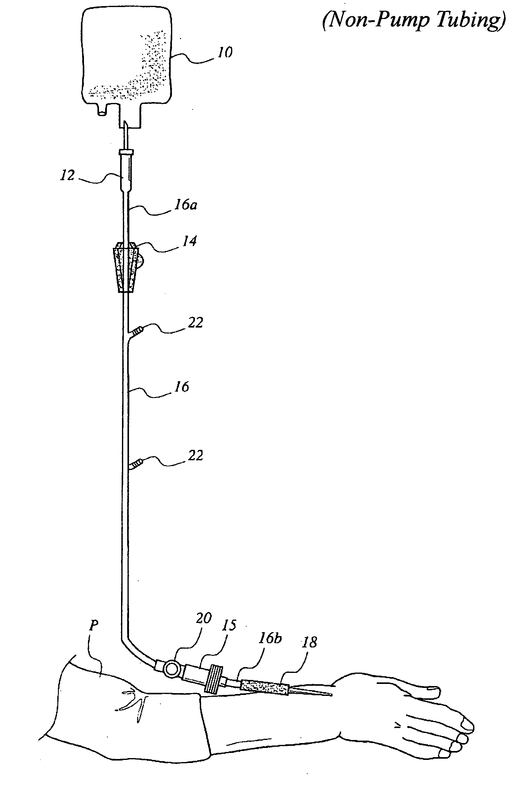
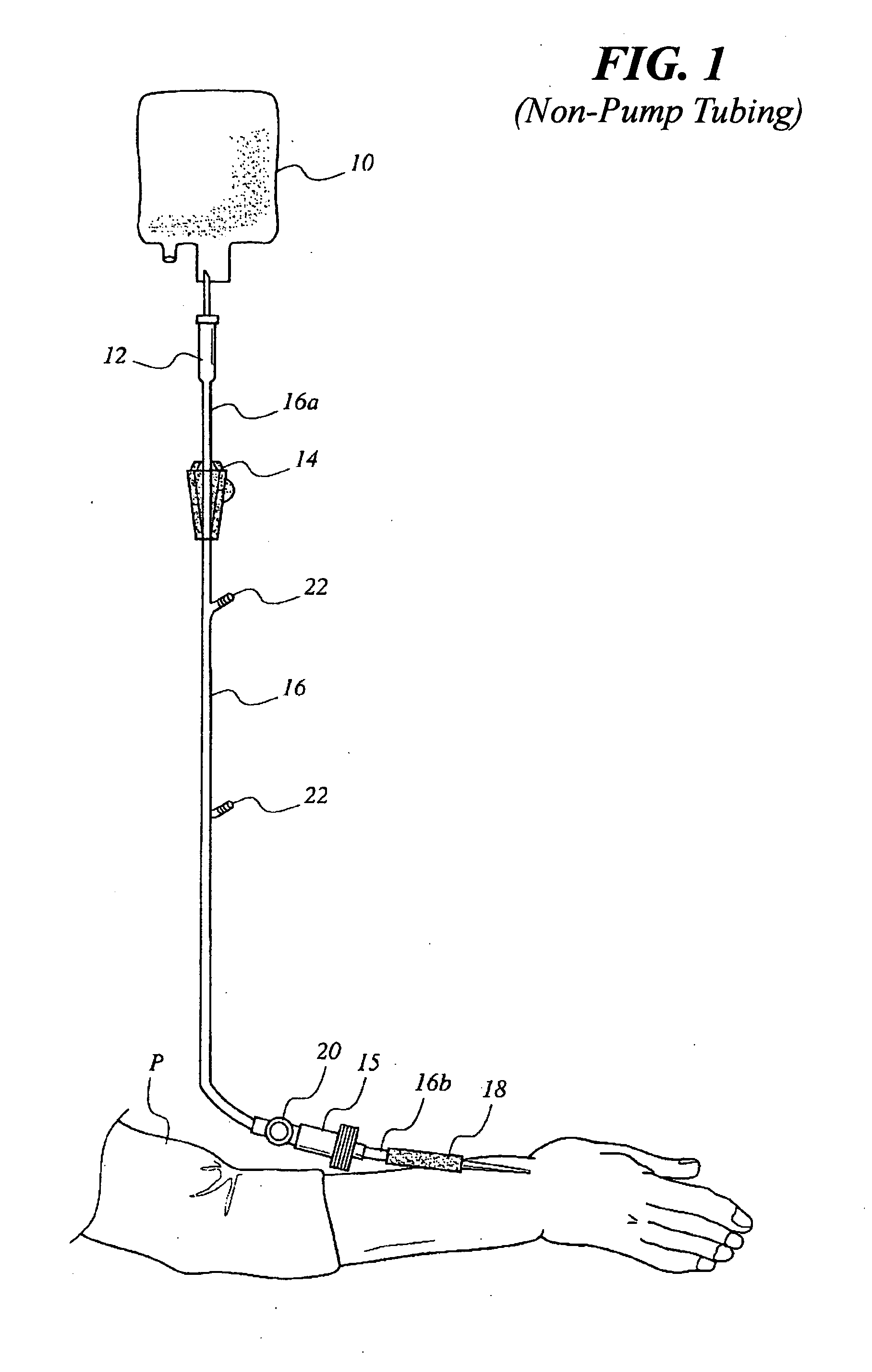
[0021] Attention is first directed to FIG. 1 wherein an I.V. system of the gravity fed type is illustrated. The system includes the conventional I.V. bag 10, drip chamber 12 and feed clamp 14. Tubing 16 has a distal end 16a opening into drip chamber 12. The proximate end 16b opens into a conventional catheter 18 via a conventional luer lock connector 15. A bubble separator 20 is positioned as close as possible to catheter 18. The only limitation as to closeness is the ability to secure the catheter to the patient P. Additional fluids may be supplied via auxiliary ports 22.

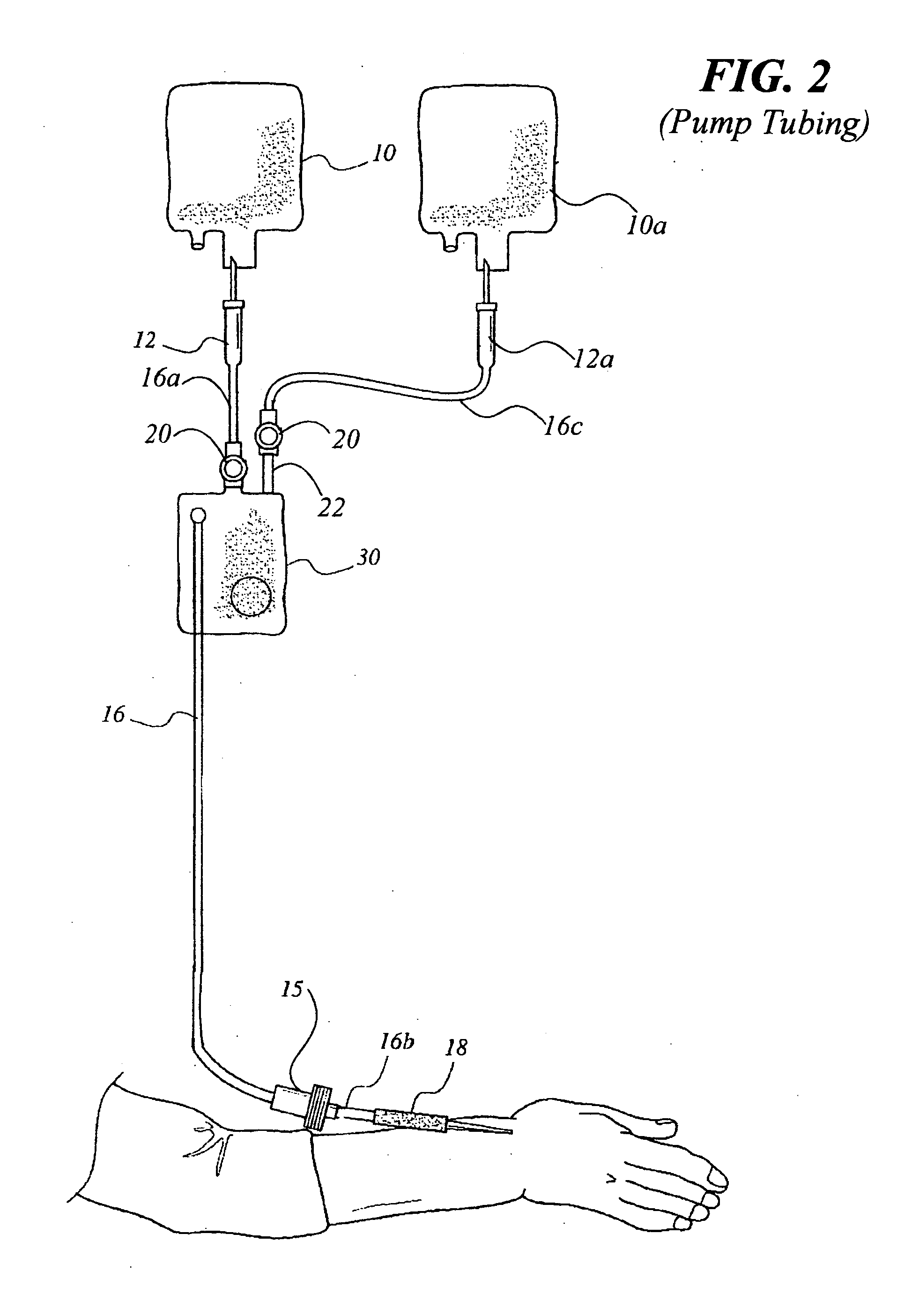
[0022] When a pump is utilized (FIG. 2), bubble separator 20 is positioned upstream of and immediately adjacent to the cassette housing 30. If fluids are to be provided via auxiliary port(s) 22, another bubble separator must be provided at the auxiliary port. Fluids are supplied to the auxiliary port from bag 10a via drip tube 12a and tubing 16c.

[0023]FIG. 3 is illustrative of one of the many prior art bubble sep...


PUM


Abstract

An intravenous tubing and air-separating valve arrangement that prevents the entry of air into the vascular system of a patient during intravenous procedures. Applicable for both pumped and non-pumped intravenous procedures, the effectiveness of the arrangement is dependent on the position of the air-separating valve relative to the patient or pump.

Description

BACKGROUND OF THE INVENTION [0001] 1. Field of the Invention [0002] The present invention generally relates to medical equipment. More specifically, the present invention is drawn to an I.V. tube and valve arrangement that minimizes the chance of bubbles entering a patient's bloodstream during an intravenous dosing or feeding procedure. [0003] 2. Description of the Related Art [0004] In hospitals and medical clinics throughout the world, thousands, if not millions of patients, daily receive medicine or other life-saving fluids intravenously (or intra-arterially). Basically, intravenous apparatus include a bag containing the fluid to be fed to the patient, tubing for transferring the fluid from the bag and an I.V. catheter for insertion in the patient (usually the arm). During the intravenous procedure, medical personnel must be constantly vigilant to prevent air bubbles which may be trapped in the fluid from entering the patient's vascular system. Such air bubbles can cause an air e...

Claims


Application Information

Patent Timeline
IPC IPC(8): A61M5/00A61M5/36
CPCA61M5/36
Inventor MICHEL, THOMAS III
Owner MICHEL THOMAS III
Features
  • Generate Ideas
  • Intellectual Property
  • Life Sciences
  • Materials
  • Tech Scout
  • Unparalleled Data Quality
  • Higher Quality Content
  • 60% Fewer Hallucinations
Learn More