
Method and device for optical ophthalmic therapy

a technology of optical ophthalmology and optical ophthalmology, applied in the field of ophthalmic treatment of patients' eyes, can solve the problems of elevated intraocular pressure, high risk of blindness, and potential debilitating effects

Active Publication Date: 2005-12-29
IRIDEX CORP
View PDF61 Cites 130 Cited by
  • Summary
  • Abstract
  • Description
  • Claims
  • Application Information

AI Technical Summary

Benefits of technology

[0012] The present invention solves the aforementioned problems by providing an optical scanning system for performing therapy on target eye tissue of a patient. The system includes a light source for producing a beam of light, a scanning device for deflecting the beam of light to produce a pattern of the light beam, and an ophthalmic lens assembly having a contact surface for contacting the patient and having a reflective optical element for reflecting the light beam pattern onto the target eye tissue.

Problems solved by technology

It is well known that glaucoma is a potentially debilitating group of ophthalmic diseases, each associated with a high risk of blindness.
Common to all of these glaucoma conditions is the inability of the trabecular meshwork (TM) to sufficiently balance the creation of aqueous humor from the ciliary body with its removal, thereby elevating intraocular pressure (IOP).
As nerve cells die, vision is slowly lost.
Often, the loss of vision is unnoticeable until significant nerve damage has occurred.
In fact, drugs don't work for many patients.
Both of these therapies are tedious and time consuming for doctor and patient, as the laser treatment spots are applied manually and sequentially.
However, this delivery of individual pulses is tedious and time consuming.
However, Hsia et al. don't address the tedious and time consuming effects of delivering individual pulses.
However, Shadduck also fails to address the tedious and time consuming effects of delivering individual pulses.
The multiple mirrors are discontinuous and separated from one another, thus creating gaps in the field of view.

Method used


Image

  • Method and device for optical ophthalmic therapy
  • Method and device for optical ophthalmic therapy
  • Method and device for optical ophthalmic therapy

Examples


Embodiment Construction

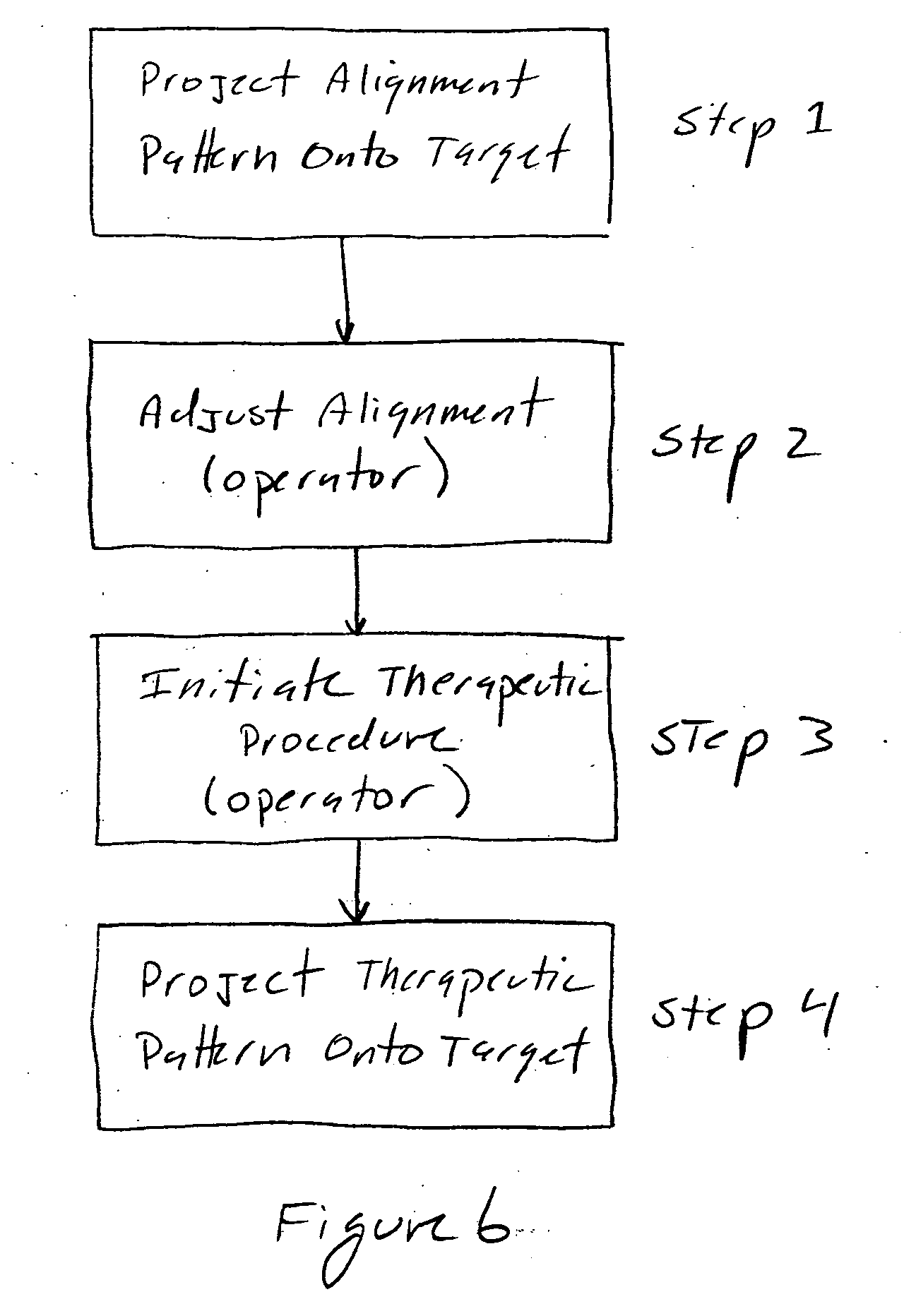
[0031] The present invention provides both instruments and methods for treating the trabecular meshwork (TM) of a patient's eye utilizing scanning optical systems. FIG. 6 is a flow diagram of a method of the present invention. In step 1, a visible alignment pattern is projected onto the TM. This alignment pattern coincides with the portions of the eye that will later be illuminated with therapeutic light, and ensures the system is properly aligned to the target portion(s) of the TM. In step 2, the user may manually adjust the alignment pattern. This step is optional, depending upon the accuracy of the original projection. Such adjustments may involve adjusting the size, scale, shape, rotation, curvature, ellipticity, etc. of the pattern and / or the spots that form the pattern to match the requirements of the particular patient contact lens used. In step 3, an initiation of the therapeutic procedure is triggered by the operator, such as by pressing a foot switch, or finger switch, etc...


PUM


Abstract

Optical scanning system and method for performing therapy on trabecular meshwork of a patient's eye, including a light source for producing alignment and therapeutic light, a scanning device for deflecting the alignment and therapeutic light to produce an alignment therapeutic patterns of the alignment and therapeutic light, and an ophthalmic lens assembly for placement over a patient's eye that includes a reflective optical element for reflecting the light patterns onto the trabecular meshwork of the patient's eye. The reflective optical element can be a continuous annular mirror (e.g. smooth or with multiple facets) to image the entire trabecular meshwork, or a reflective optical element that moves in coordination with the deflection of the beam. Visualization of the alignment and therapeutic patterns of light on the eye can be implemented by reflection thereof off a visualization mirror that transmits a portion of light emanating from the trabecular meshwork.

Description

[0001] This application claims the benefit of U.S. Provisional Application No. 60 / 583,436,filed Jun. 28, 2004.FIELD OF THE INVENTION [0002] The present invention pertains generally to the ophthalmic treatment of a patient's eye, and more particularly to photomedical treatment of the trabecular meshwork of a patient's eye at multiple locations. BACKGROUND OF THE INVENTION [0003] It is well known that glaucoma is a potentially debilitating group of ophthalmic diseases, each associated with a high risk of blindness. These conditions include, but are not limited to: open-angle glaucoma, exfoliation glaucoma, and pigmentary glaucoma. Common to all of these glaucoma conditions is the inability of the trabecular meshwork (TM) to sufficiently balance the creation of aqueous humor from the ciliary body with its removal, thereby elevating intraocular pressure (IOP). The ocular hypertension associated with glaucoma causes a gradual degeneration of cells that make up the optic nerve. As nerve c...

Claims


Application Information

Patent Timeline
IPC IPC(8): A61B18/20A61F9/007A61F9/008A61H5/00A61H33/00
CPCA61B2018/00636A61B2018/2085A61H5/00A61F9/00821A61F2009/00868A61F9/00781A61B3/117A61B2018/20351A61B2018/205545A61B2018/20359
Inventor ANDERSEN, DAN E.MORDAUNT, DAVID H.WILTBERGER, MICHAEL W.
Owner IRIDEX CORP
Learn More