Steel strip for razor blades and method of manufacturing the same

a technology of stainless steel and razor blades, which is applied in the direction of manufacturing tools, furnaces, heat treatment equipment, etc., can solve the problems of increasing the abrasion of the slitting knife, and the inability to increase the feeding rate of the raw material strip, so as to achieve constant cross section, increase the feeding rate of the strip, and high precision

Active Publication Date: 2006-01-05
HITACHI METALS LTD
View PDF6 Cites 18 Cited by
  • Summary
  • Abstract
  • Description
  • Claims
  • Application Information

AI Technical Summary

Benefits of technology

[0014] The splitting portion of the strip for the present invention is constituted as the continuous processed groove formed with the thermal energy in the longitudinal direction of the strip. Thus, the splitting portion of the strip is formed to have a substantially constant form in cross section over the whole length of the strip. The present invention has advantages that it prevents a problem that when the strip is split, the strip partially remains connected without separating.
[0015] Additionally, because the continuous processed groove is formed by thermal energy (for example by laser beam) the splitting portion of the strip is processed without any contact and with high precision. By selecting a laser beam machine, the feeding rate of the strip can be increased as compared with conventional methods. Therefore, the present invention provides excellent productivity.

Problems solved by technology

Moreover, there poses a problem that abrasion of the slitting knives increases as the feeding rate of the strip of raw material increases.
Thus, it is impossible to increase the feeding rate of the strip of raw material.

Method used


Image

  • Steel strip for razor blades and method of manufacturing the same
  • Steel strip for razor blades and method of manufacturing the same
  • Steel strip for razor blades and method of manufacturing the same

Examples


examples

[0072] Hereinafter, the present invention will be explained through the result of experiments.

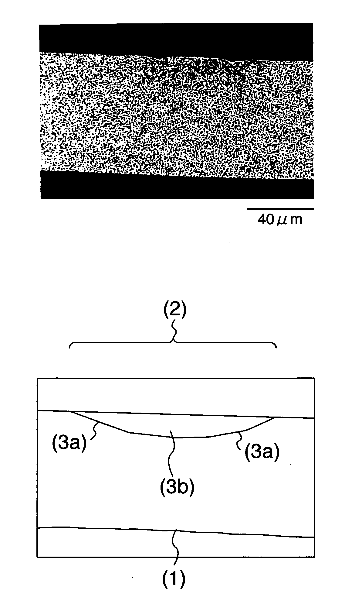
[0073] Ingots (No. 1 and No. 2 alloys) of martensitic stainless steels manufactured by melting in ambient atmosphere were forged and hot rolled, and oxidized scales formed in the hot working were removed, to thereby obtain raw materials for cold rolling.

[0074] The raw materials were cold rolled and annealed repeatedly. After the finally annealing, they were finish rolled at a reduction rate of 18%, thereby obtaining raw material having a thickness of 0.08 mm and a width of 6 mm for steel strips for the razor blades. Chemical compositions of alloys are shown in Table 1.

[0075] Metallographic structures of both alloys of the steel strips for razor blades have ferritic structures. Hardness, in Vickers hardness, of the alloy No. 1 was HV280 and that of the alloy No. 2 was HV290, and in a state where the strips could be wound into coils.

TABLE 1Alloy No.CSiMnCrMoBalance10.480.460.9013.71.25Fe...


PUM

PropertyMeasurementUnit
depthaaaaaaaaaa
widthaaaaaaaaaa
widthaaaaaaaaaa

Abstract

The present invention provides a martensitic stainless steel strip for razor blades in annealed state comprising a continuous processed groove being formed with thermal energy in a longitudinal direction on one side of the strip at a position with a predetermined distance from one edge; and a continuous changed structure area being formed with thermal energy in a longitudinal direction on opposite side of the strip at a position having a predetermined distance from the edge, wherein the processed groove functions as a splitting portion of the strip. In addition, the present invention provides a method for manufacturing the steel strip for razor blades.

Description

TECHNICAL FIELD [0001] The present invention relates to martensitic stainless steel strips for razor blades and method of manufacturing the same. BACKGROUND OF INVENTION [0002] The Conventional production of razor blades cuts a steel strip mechanically. [0003] JP-A-9-510401 entitled “RAZOR BLADE MANUFACTURE”, for example, discloses a manufacturing method of razor blades, in which a coil employed as a raw material is stamped, straight grooves (openings) are formed by slitting knives, then heat-treated for hardening, and finally split into end-products. [0004] The method is excellent for improving productivity, because forming grooves, hardening, and splitting are sequentially processed on a coiled steel strip. [0005] With regard to the steel strip employed as a raw material in the method disclosed in JP-A-9-510401, grooves are formed on an as-rolled steel strip by the slitting knives. In this case the slitting knives must be positioned with high precision. Moreover, there poses a pro...

Claims


Application Information

Patent Timeline
Patent Type & Authority Applications(United States)
IPC IPC(8): C22C38/18B21D53/64B23K26/08B26B21/00B26B21/58C21D1/18C21D6/00C21D8/02C21D8/04C21D9/18C21D10/00
CPCB23K26/0846B23K2203/04B26B21/58C21D1/18C21D6/002C22C38/22C21D2211/008C22C38/02C22C38/04C22C38/18C21D8/0436B23K2103/05
Inventor YOSHIYAMA, GOH
Owner HITACHI METALS LTD
Why Eureka
Try Eureka