Apparatus for peeling release film

Inactive Publication Date: 2006-01-05
INNOLUX CORP
View PDF7 Cites 9 Cited by
  • Summary
  • Abstract
  • Description
  • Claims
  • Application Information

AI Technical Summary

Benefits of technology

[0009] In light of the above, one objective of the present invention is to provide a release film peeling apparatus tha

Problems solved by technology

When such deviation occurs, the process of peeling the release fil

Method used


Image

  • Apparatus for peeling release film
  • Apparatus for peeling release film
  • Apparatus for peeling release film

Examples


first embodiment

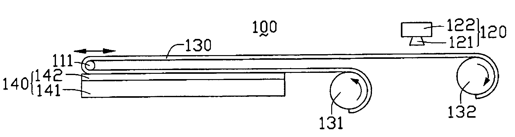
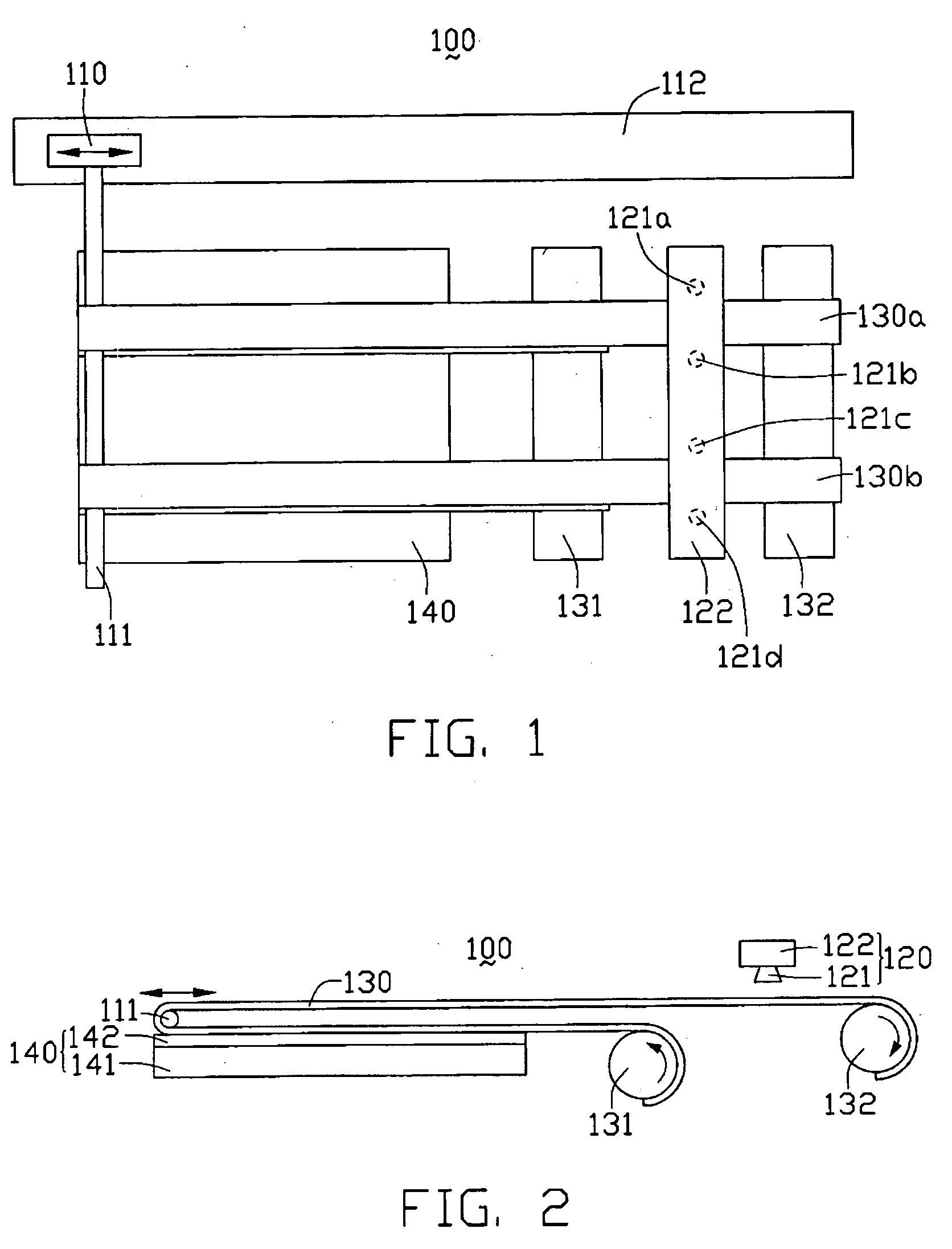
[0021] Referring to FIG. 1 and FIG. 2, a top elevation view and a side elevation view of a release film peeling apparatus 100 according to the invention are shown. The release film peeling apparatus 100 comprises a first roller 131, a second roller 132, a motion driver 110, a rod 111, a guiding track 112, a detecting means 120, and two tapes 130. The two tapes 130 are a first tape 130a and a second tape 130b. The tapes 130 adhere on a release film 142 of a polarization plate 140. A strength of the adhesion is greater than that of an adhesion of the release film 142 on a polarization film 141 of the polarization plate 140.

[0022] The detecting means 120 comprises a mount 122, and a plurality of detectors 121 installed on the mount 122. In the first embodiment, four detectors 121a, 121b, 121c and 121d are provided for detecting any deviations of the tapes 130. In embodiments, even one detector 121 only may be sufficient for achieving the function of detecting any deviations of the tape...

second embodiment

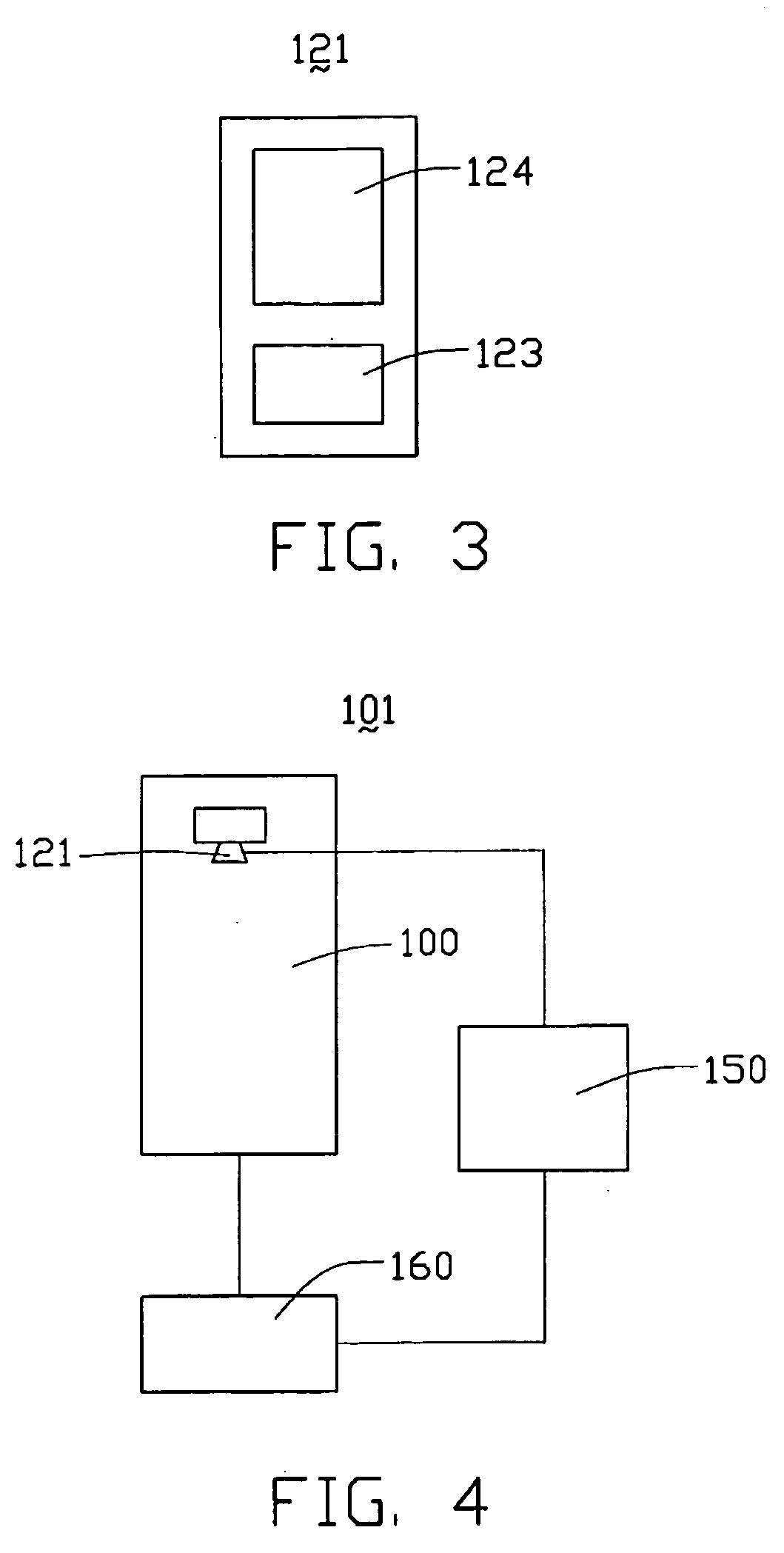
[0028] Referring to FIG. 4, an enhanced release film peeling apparatus 101 according to the invention is schematically illustrated. The enhanced release film peeling apparatus 101 comprises the release film peeling apparatus 100, a control unit 150, and a power supply 160.

[0029] In operation of the release film peeling apparatus 101, once any deviation of the tapes 130 is detected by the corresponding light beam sensor 124, the corresponding detector 121 sends out a deviation signal to the control unit 150. The control unit 150 then processes the received signal and sends out a switching signal to the power supply 160, which switches off the driving power to the release film peeling apparatus 100. The control unit 150 also sends out a signal to an alarm device such as a loudspeaker (not shown), so as to alert relevant personnel of the occurrence of the tape deviation.

[0030] In summary, with the utilization of the detecting means 120 in the release film peeling apparatus 100, any ab...


PUM

PropertyMeasurementUnit
Tensionaaaaaaaaaa

Abstract

An apparatus (101) for peeling release films (142) used in the manufacturing of liquid crystal display devices includes a winding mechanism for winding a pair of tapes (130) to peel a release film off from a polarization plate (141), a release film peeling mechanism, and a detecting means (120) having a mount (122) and several detectors (121). The detectors are installed on the mount for detecting any deviation of the tape. When a deviation occurs, the relevant detector sends a signal to a control unit (150). The control unit then sends out a signal to a power supply (160) of the apparatus to turn off the apparatus. The control unit also sends out a signal to an alarm device, so as to alert relevant personnel of the occurrence of the deviation.

Description

BACKGROUND OF THE INVENTION [0001] 1. Field of the Invention [0002] The present invention relates generally to apparatuses for manufacturing liquid crystal display devices, and more particularly to an apparatus for peeling release films off from polarization plates. [0003] 2. Description of the Prior Art [0004] Manufacturing liquid crystal display devices comprises many processing steps. Among them, there is a process of gluing a polarization film onto a liquid crystal display panel (or liquid crystal cell). For conveniently gluing the polarization film onto the liquid crystal display element, a polarization plate comprising an adhesive polarization film and a release film is provided. [0005] As shown in FIG. 5, a polarization plate 40 comprises an adhesive polarization film 41 and a release film 42. The adhesive polarization film 41 comprises an adhesive surface 43 contacting the release film 42, for gluing the polarization film 41 onto the liquid crystal display element. [0006] In...

Claims


Application Information

Patent Timeline
IPC IPC(8): B29C63/00H01L21/301H01L21/46
CPCB29C63/0013Y10T156/1906Y10T156/1105H01L21/67132
Inventor YAO, KUO-MINGSUNG, CHEN-CHILIN, CHIA-HSINYU, YIU-CHINCHANG, MAO-JUIYANG, HSIN-JUNG
Owner INNOLUX CORP
Why Eureka
Try Eureka