Radio frequency tags for turbulent flows

a radio frequency tag and turbulent flow technology, applied in the field of radio frequency tags for turbulent flows, can solve the problems of not coupling to the field produced by the reader antenna, losing contact with the reader, and frequency attenuation in conductive fluids

Inactive Publication Date: 2006-01-05
SCHLUMBERGER TECH CORP
View PDF10 Cites 47 Cited by
  • Summary
  • Abstract
  • Description
  • Claims
  • Application Information

AI Technical Summary

Benefits of technology

[0018] In a preferred embodiment of this aspect of the invention, the antennas are connected by an electronic circuit designed to pass through to the RFID tag the signal from the antenna with the strongest coupling and, hence, best reception from the reader antenna.

Problems solved by technology

The use of RFID tags in well bore flows poses a number of challenges not encountered in the field of inventory control and device tracking where such tags are commonly applied.
However as a tag in a turbulent flow will tumble, it may not couple to the field produced by the reader antenna.
In a turbulent flow it is likely that the tag changes its orientation during the read-out phase thus losing contact with the reader.
While it is possible to shorten the read times by using higher frequencies, such frequencies have a higher attenuation in conductive fluids and are therefore not a practical solution for many oilfield applications.

Method used


Image

  • Radio frequency tags for turbulent flows
  • Radio frequency tags for turbulent flows
  • Radio frequency tags for turbulent flows

Examples


examples

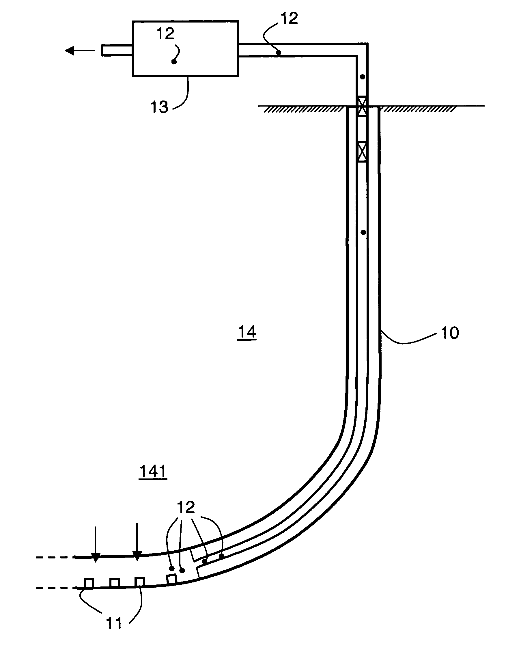
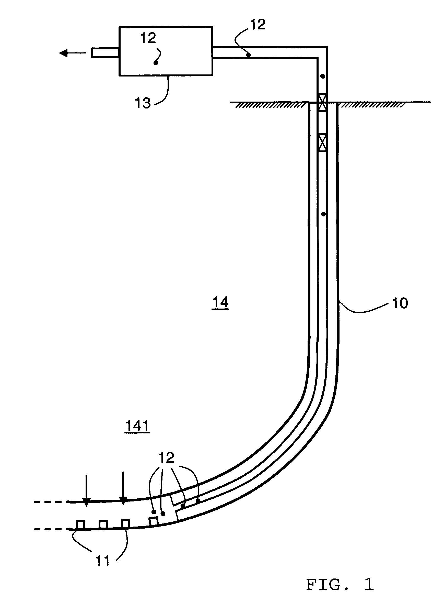
[0036] In FIG. 1 there is shown a system for communicating information from downhole to the surface. The system generally comprises one or more downhole sensors and associated release mechanisms 11, floating passive autonomous devices or vessels 12, and surface detection system 13. There are four sensor / release mechanisms 11 positioned in the lower end of well 10. Well 10 is producing hydrocarbons from reservoir region 141 in the earth 14. The vessels 12 are constructed to have a high probability of surviving downhole pressures and temperatures, and will be carried to the surface by the flowing liquids in the well 10. Surface detection system 13 detects and / or recovers vessels and interprets the signals conveyed by vessels 12.

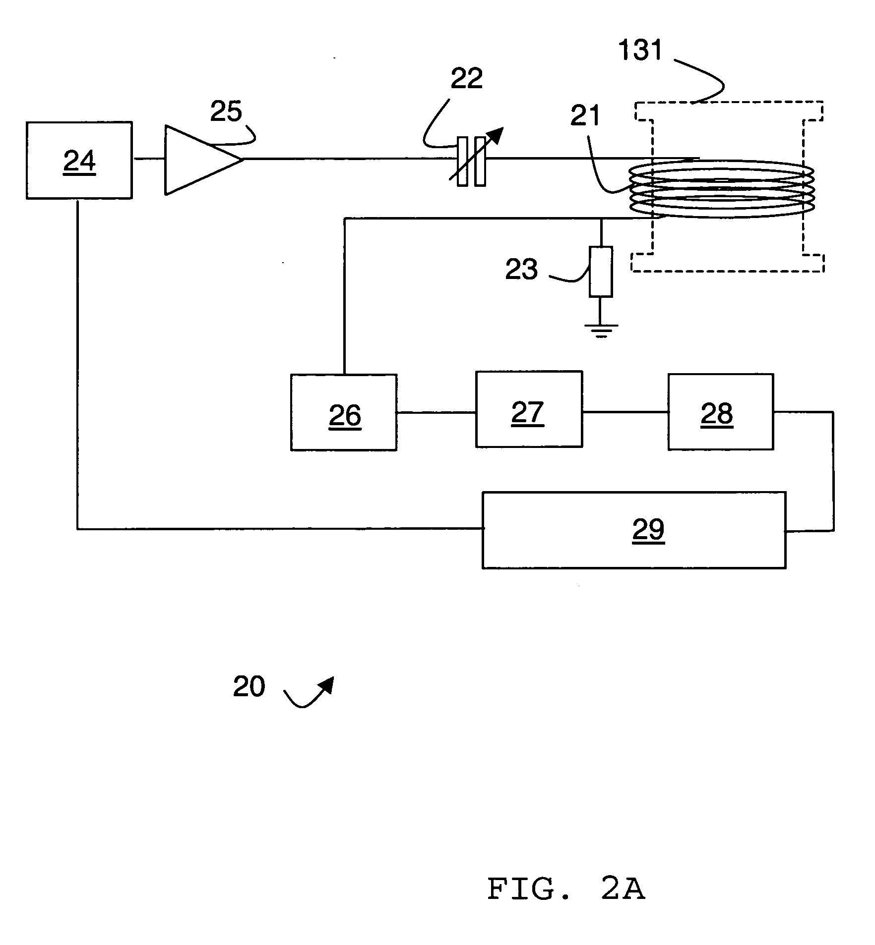
[0037] Reader circuit 20 of surface detection system 13 is shown in greater detail in FIG. 2A. The reader circuit includes reader coil 21 of 170 mm length and 90 mm diameter. It is wound with approximately 440 turns of 0.3 mm insulated copper wire mounted onto...


PUM


Abstract

A system for communicating information, particular for use in a hydrocarbon well, is described including one or more releasable vessels having radio frequency (RF) circuitry responsive, when in use, to an RF reader system, the vessel including counteracting means to reduce the effect of destabilizing flow forces thereby extending the coupling time with the reader system.

Description

[0001] This application claims priority from United Kingdom Patent Application No. 0412927.6, filed Jun. 9, 2004. [0002] The present invention generally relates to apparatus and methods for transmitting information using a radio frequency transponder in a turbulent flow environment. More specifically, it relates to such apparatus and methods to carry information through a flow of well bore effluents. BACKGROUND OF THE INVENTION [0003] Radio frequency identification (RFID) tags are found in an ever-increasing number of applications within a wide variety of different environments. Within the oilfield such tags can be used to identify equipment and / or transfer information along the well bore. The use of RFID tags in well bore flows poses a number of challenges not encountered in the field of inventory control and device tracking where such tags are commonly applied. [0004] The flow of effluents from the well bore is often turbulent and the effluents may consist of multiple phases such ...

Claims


Application Information

Patent Timeline
Patent Type & Authority Applications(United States)
IPC IPC(8): E21B47/00E21B47/12H04H
CPCE21B47/122E21B47/12E21B47/13E21B47/138
Inventor JENKINS, CHARLESBARRETTBARROW, HARRYDICKENSON, PAULJOHNSON, ASHLEY
Owner SCHLUMBERGER TECH CORP
Why Eureka
Try Eureka