Electronic control unit and system for controlling dual-stage occupant restraint system

Inactive Publication Date: 2006-01-05
DENSO CORP
View PDF10 Cites 17 Cited by
  • Summary
  • Abstract
  • Description
  • Claims
  • Application Information

AI Technical Summary

Benefits of technology

[0008] It is therefore an object of the present invention to provide an electronic con

Problems solved by technology

Since it is desired that the number of channels for connecting the dual-stage firing module 102 to the ECU 101 be as small as possible to simplify the vehicle's harness, the

Method used


Image

  • Electronic control unit and system for controlling dual-stage occupant restraint system
  • Electronic control unit and system for controlling dual-stage occupant restraint system
  • Electronic control unit and system for controlling dual-stage occupant restraint system

Examples


Embodiment Construction

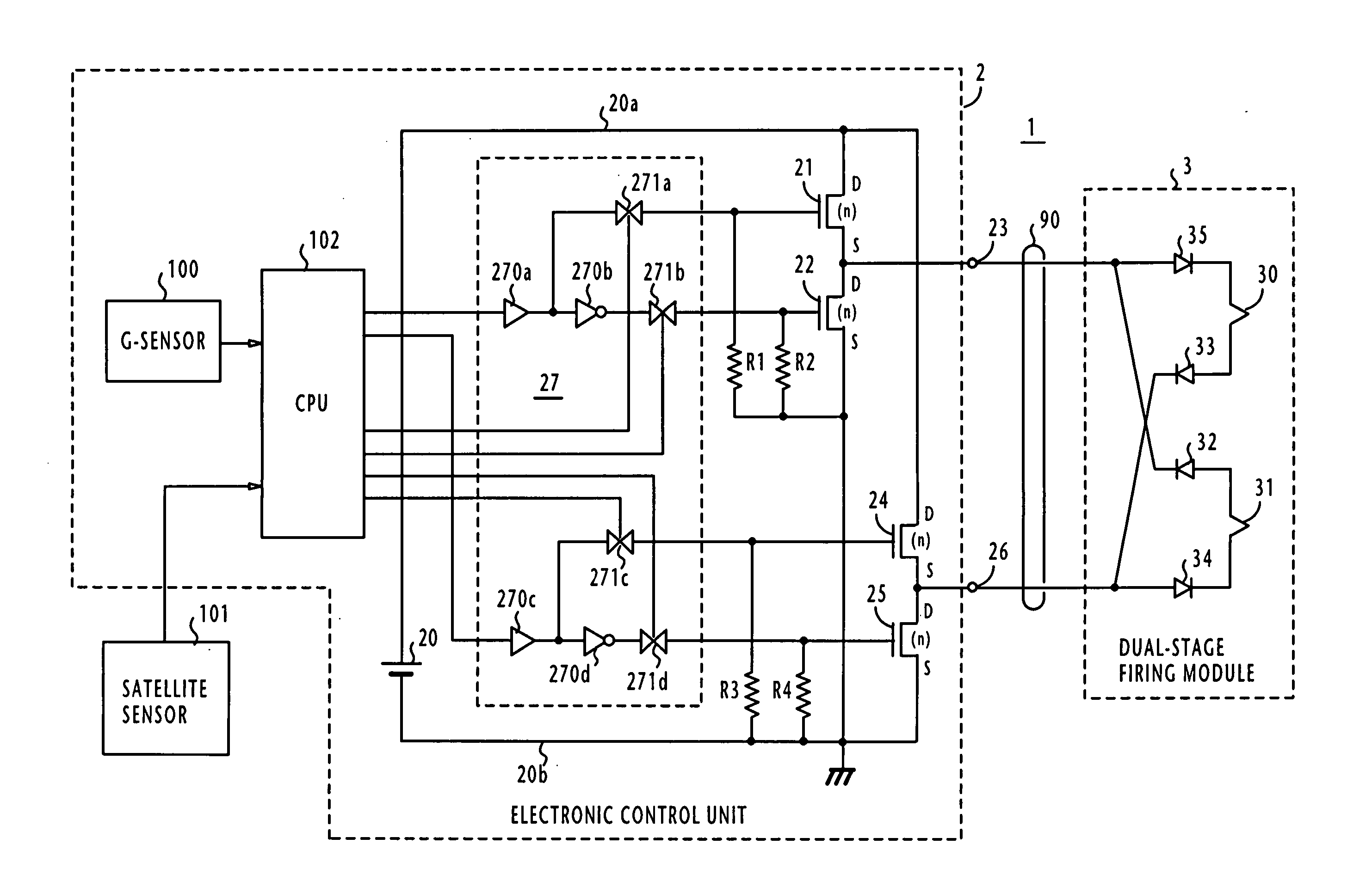
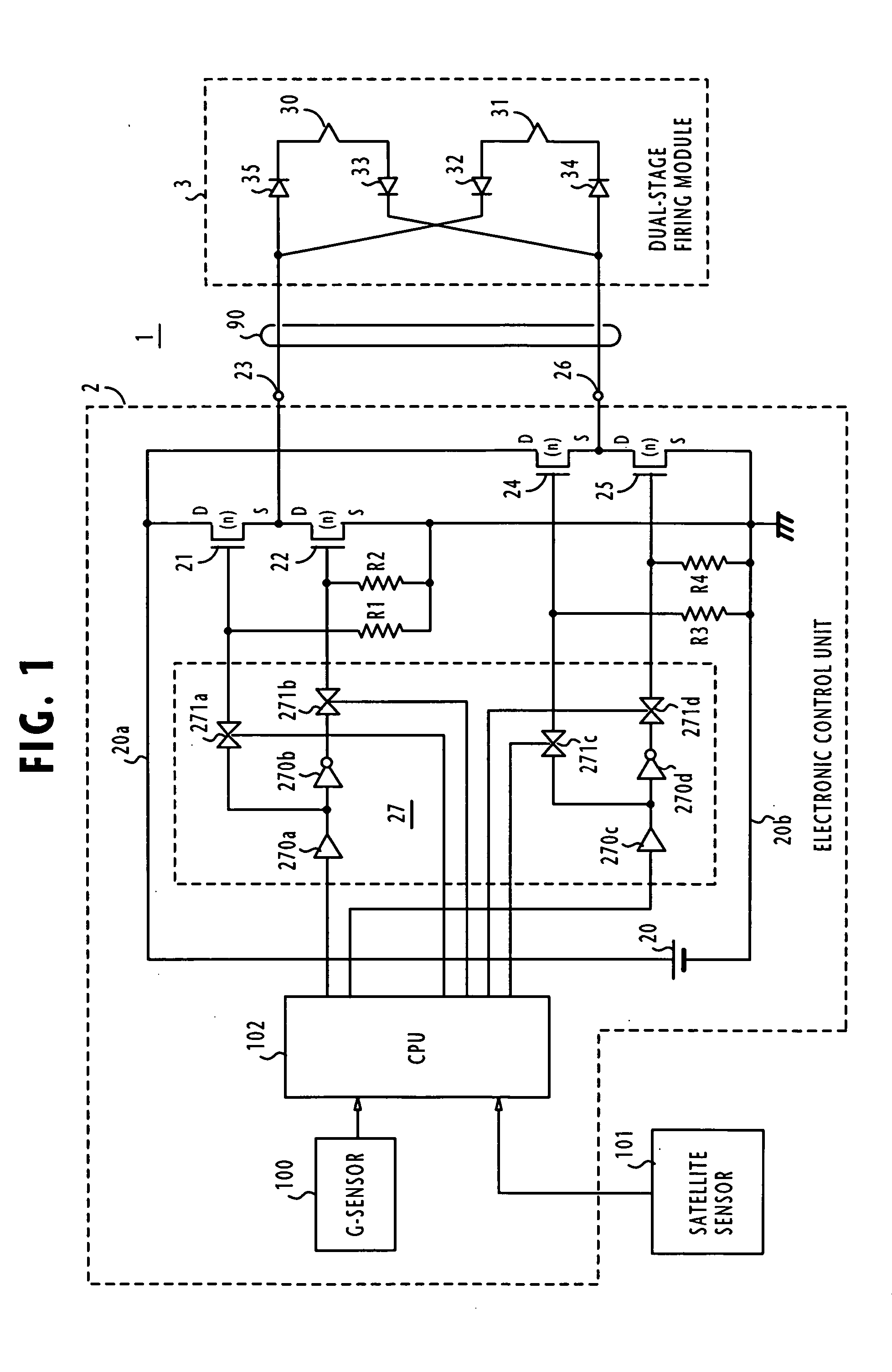
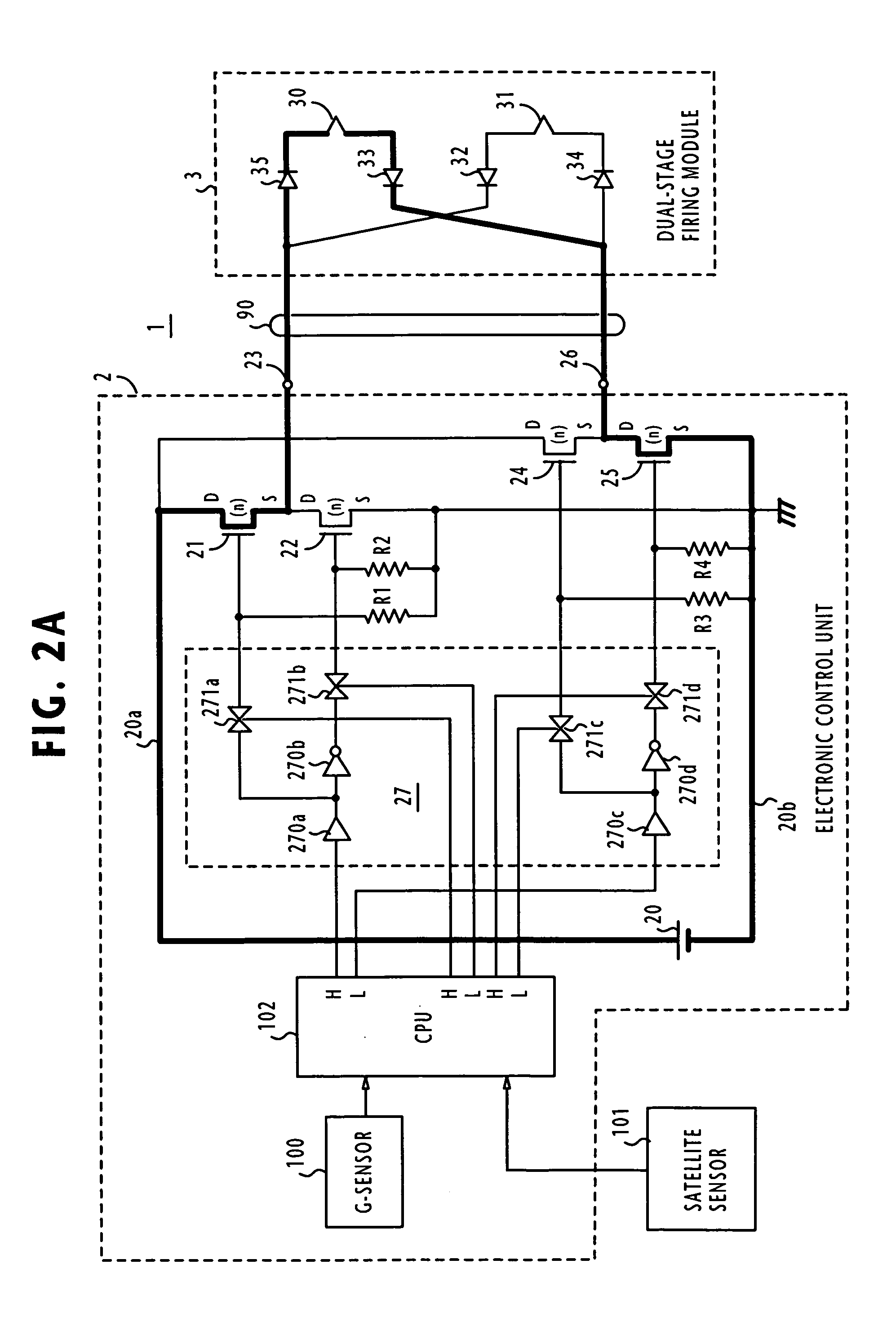
[0026] In FIG. 1, there is shown a control system for a dual-stage vehicle occupant restraint system according to one embodiment of the present invention. The control system, generally designated as 1, includes an electronic control unit 2 and a dual-stage firing module 3. ECU 2 is mounted on the instrument panel of a passenger vehicle and the firing module 3 is mounted on the midpoint of the steering wheel. Although not shown, an inflator and an airbag system are folded into the steering wheel.

[0027] The number of channels between the ECU 2 and the dual-stage firing module 3 is reduced and advance is made over the prior art by initially supplying a forward current from the ECU 2 to the firing module 3 to activate the first stage of the module 3 and then supplying a reverse current to the firing module 3 to activate its second stage. The first and second stages of firing mode 3 respectively include squids 30 and 31.

[0028] Electronic control unit 2 includes an impact sensor known a...


PUM


Abstract

In a control system for a dual-stage airbag firing system, a series circuit of first and second switching elements and a series circuit of third and fourth switching elements are connected in parallel between high and low voltage power lines, the circuit node between the switching elements of each series circuit being connected to a corresponding one of a pair of output terminals. When an impact is received, the first and fourth switching elements are exclusively activated to generate a forward voltage across the output terminals, causing a forward current to flow in the firing system so that its first stage is exclusively fired. Subsequently, the third and second switching elements are exclusively activated to generate a reverse voltage across the output terminals in a direction opposite to the forward voltage, causing a reverse current to flow in the firing system so that its second stage is fired.

Description

CROSS-REFERENCE TO RELATED APPLICATION [0001] This application is related to Japanese Patent Application No. 2004-193125 filed on Jun. 30, 2004, the contents of which is hereby incorporated by reference. BACKGROUND OF THE INVENTION [0002] 1. Field of the Invention [0003] The present invention relates to an electronic control unit and a system for the protection of vehicle occupants using a restraint system including a dual-stage airbag and / or seat belt pretensioner having both driver and passenger side firing circuits. [0004] 2. Description of the Related Art [0005] U.S. Pat. No. 5,187,465 discloses a dual airbag restraint system having two firing circuits for independently operating a driver-side squib and a passenger-side squib. [0006] Also known is a dual-stage airbag restraint system in which a single airbag is deployed in stages, initially on a driver side and subsequently on a passenger side. As illustrated in FIG. 9, the prior art dual-stage airbag control system is comprised...

Claims


Application Information

Patent Timeline
IPC IPC(8): B64D25/115
CPCB60R21/017
Inventor OOYABU, SHINJI
Owner DENSO CORP
Why Eureka
Try Eureka