Echo sounder transducer

a transducer and sound technology, applied in the field of echo sounder transducers, can solve the problems of not being able to achieve wideband operation with securing a sound, not being able to perform acoustic radiation, and not being able to so as to achieve a high sound pressure level and widen the frequency band

Active Publication Date: 2006-01-05
NEC CORP
View PDF4 Cites 21 Cited by
  • Summary
  • Abstract
  • Description
  • Claims
  • Application Information

AI Technical Summary

Benefits of technology

[0042] Thereby, in the Langevin-type echo sounder transducer which can perform low-frequency acoustic wave radiation using the bend vibration mode of the bend vibrator, and the longitudinal vibration mode of the whole echo sounder transducer without upsizing the dimensions of the echo sounder transducer, it becomes possible to widen a frequency band by raising a sound pressure level in a frequency band between the resonance frequencies in these two vibration modes (intermediate area). Hence, it becomes possible to achieve a wide bandwith securing a high sound pressure level from a low frequency area.

Problems solved by technology

Nevertheless, in a conventional Langevin-type echo sounder transducer like the above, there arose a problem that, first, in the case of the conventional echo sounder transducer shown in FIG. 12, since the coupling of vibration modes arose because of integral structure of the Langevin-type vibrator and bend vibrator, it was not possible to achieve wideband operation with securing a sound pressure level beyond a certain level.
Therefore, there arose a problem that acoustic radiation could not be performed.
For this reason, a sound pressure level in a frequency band (intermediate area) between a resonance frequency of the bend vibrator in the bend vibration mode and a resonance frequency of the echo sounder transducer in the longitudinal vibration mode dropped remarkably, and hence, it was not possible to widen the frequency band so that the sound pressure level beyond a certain level could be obtained.

Method used


Image

  • Echo sounder transducer
  • Echo sounder transducer
  • Echo sounder transducer

Examples


first embodiment

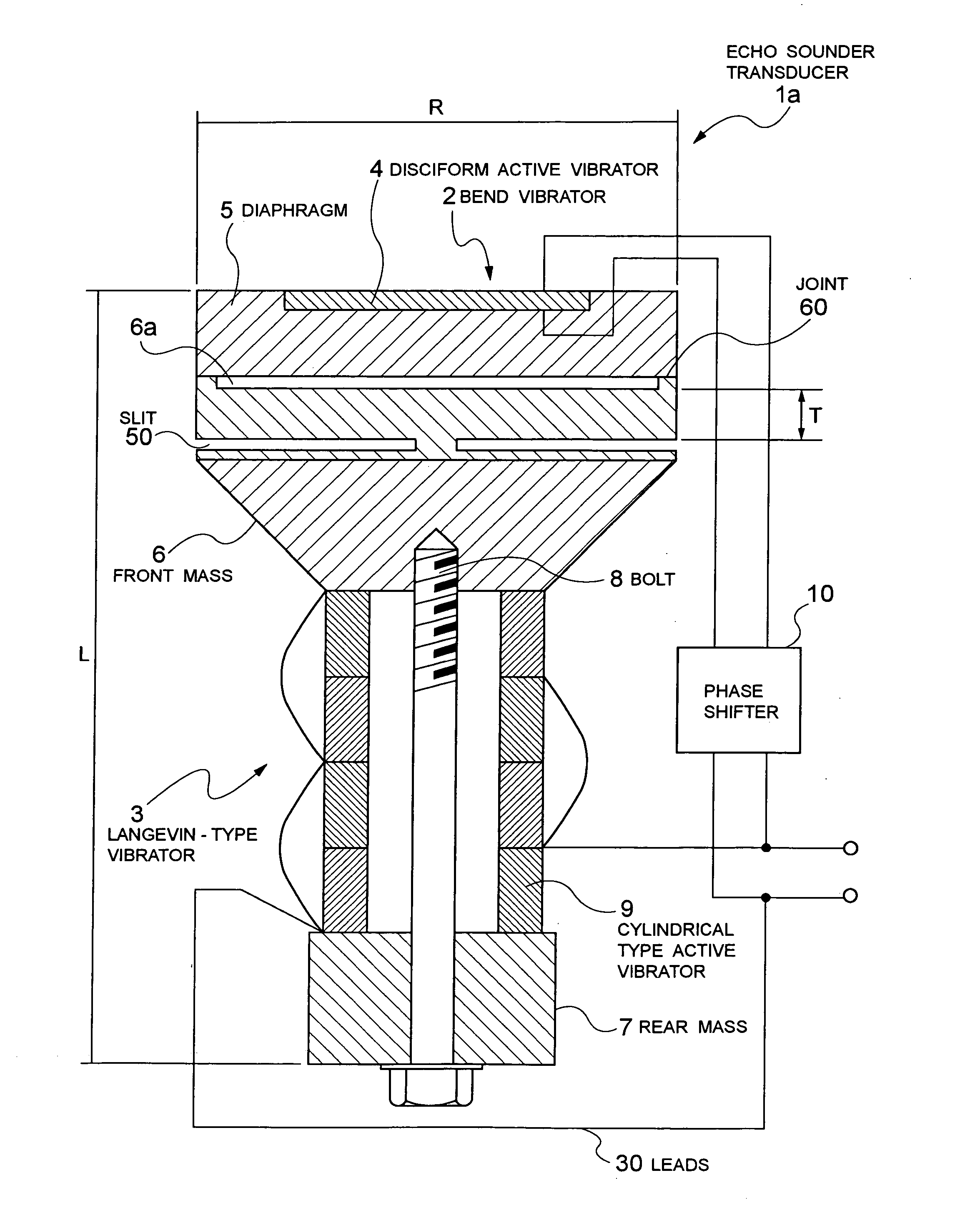
[0057] First, a first embodiment of an echo sounder transducer according to the present invention will be described with referring to FIGS. 1 to 3.

[0058]FIG. 1 is a schematic sectional diagram of the echo sounder transducer according to the first embodiment of the present invention.

[0059] As shown in this figure, the present invention is a Langevin-type echo sounder transducer, and an echo sounder transducer la is an echo sounder transducer which is equipped with a Langevin-type vibrator 3, and is further equipped with a bend vibrator 2 on a front section, that is, an acoustic radiation surface section of the Langevin-type vibrator 3.

[0060] The appearance of this echo sounder transducer la is the same as that of the echo sounder transducer shown in FIG. 11 mentioned above.

[0061] The Langevin-type vibrator 3, as shown in FIG. 1, is equipped with a front mass 6 and a rear mass 7, and a cylindrical active vibrator 9 which is constituted of a piezoelectric ceramic stacked body and t...

second embodiment

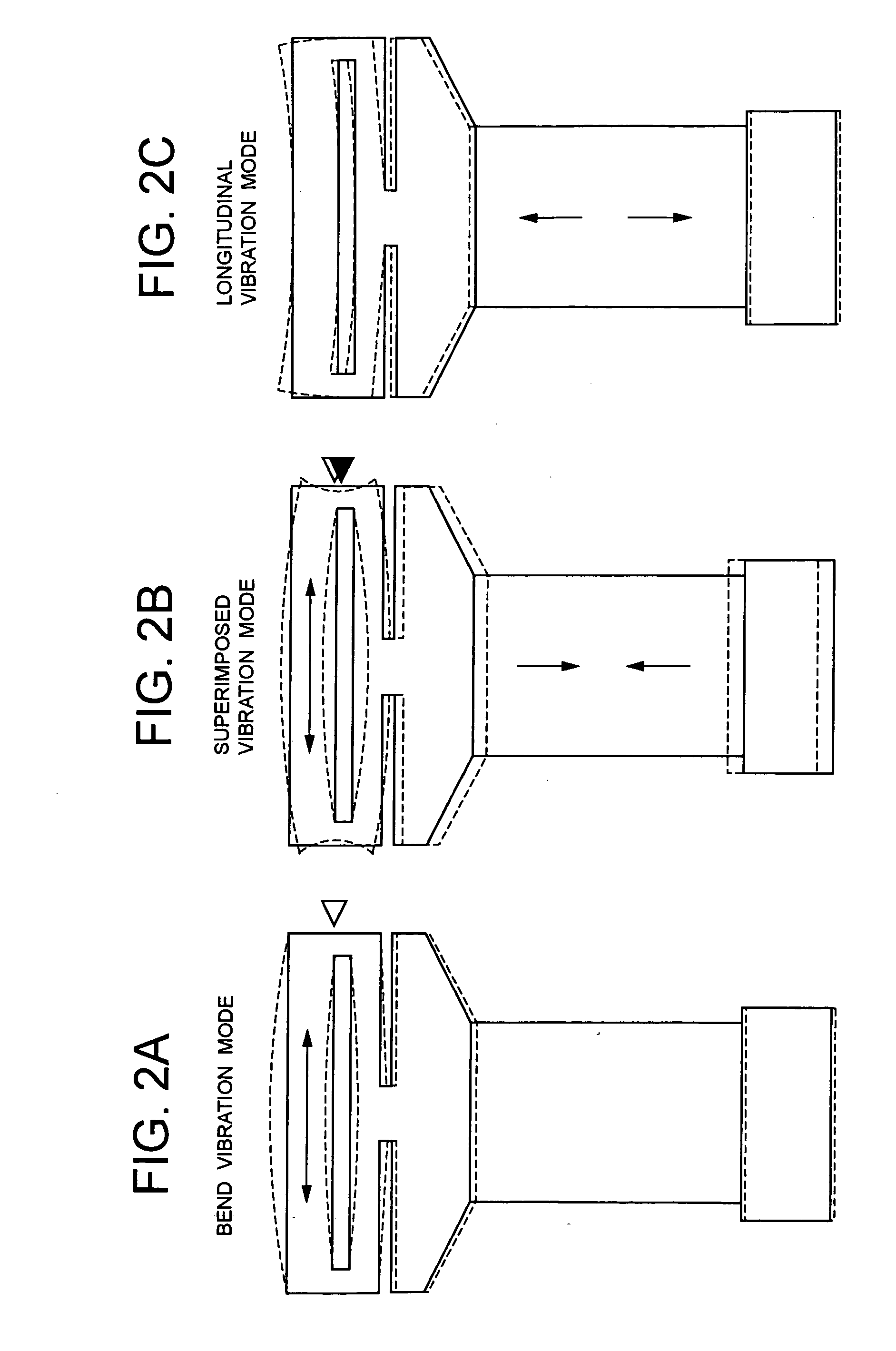
[0096] Next, a second embodiment of an echo sounder transducer according to the present invention will be described with referring to FIG. 4.

[0097]FIG. 4 is a schematic sectional diagram of the echo sounder transducer according to the second embodiment of the present invention, and FIGS. 5A to 5C include explanatory diagrams of vibration modes of the echo sounder transducer shown in FIG. 4. FIGS. 6A to 6D include explanatory diagrams showing the states of the endpoint supporting section at the time of vibration of the echo sounder transducer shown in FIG. 4 in comparison with the states of an ordinary echo sounder transducer.

[0098] The echo sounder transducer 1b according to this embodiment shown in these figures is a modified embodiment of the first embodiment mentioned above, and endpoint supporting sections 20 are provided as connecting means of the front mass 6 of the Langevin-type vibrator 3 and the bend vibrator 2 instead of the joint 60 shown in the first embodiment.

[0099]...

third embodiment

[0107] Further, a third embodiment of an echo sounder transducer according to the present invention will be described with referring to FIGS. 7, 10A and 10B.

[0108]FIG. 7 is a schematic sectional diagram of the echo sounder transducer according to the third embodiment of the present invention, and FIG. 8 is a partially schematic perspective view of a composite ring with which the echo sounder transducer shown in FIG. 7 is equipped.

[0109] In addition, FIG. 9 is an explanatory diagram showing schematically the operation of the composite ring with which the echo sounder transducer shown in FIG. 7 is equipped, and FIGS. 10A and 10B are explanatory diagrams showing schematically the operation of the echo sounder transducer shown in FIG. 7 similarly.

[0110] As shown in these figures, an echo sounder transducer 1c according to this embodiment is a modified form of the first embodiment mentioned above, and a composite ring 70 is added to the echo sounder transducer 1a shown in FIG. 1.

[011...


PUM


Abstract

The present invention achieves the wideband operation of a bolted Langevin-type echo sounder transducer by enabling low frequency operation with securing a sound pressure level above a certain level without changing the external dimensions of the echo sounder transducer. This is an echo sounder transducer includes a Langevin-type vibrator having a front mass and a rear mass, and a cylindrical active vibrator which is sandwiched between the front mass and rear mass, a bend vibrator constituted of a diaphragm arranged in an acoustic radiation surface section of the front mass of the Langevin-type vibrator, and a disc type active vibrator fixed to the diaphragm. This has such structure that a slit, communicating from an outer peripheral side face toward an axial center, is provided on the circumference in the side of the lower portion of the front mass of the Langevin-type vibrator toward the rear mass.

Description

BACKGROUND OF THE INVENTION [0001] 1. Field of the Invention [0002] The present invention relates to an echo sounder transducer which emits an acoustic wave underwater by electroacoustic transduction, and in particular, to an echo sounder transducer suitable for the wideband operation of a Langevin-type echo sounder transducer which enables low frequency operation with securing a sound pressure level beyond a certain level without changing the external dimensions of the echo sounder transducer. [0003] 2. Description of the Prior Art [0004] Generally, a Langevin-type echo sounder transducer is known as an echo sounder transducer which emits an acoustic wave underwater by electroacoustic transduction. [0005] The Langevin-type echo sounder transducer is equipped with a bolted Langevin-type vibrator as vibration generating means, and emits an acoustic wave in a predetermined frequency band by applying a compressive stress to a piezoelectric ceramic stacked body sandwiched between a fron...

Claims


Application Information

Patent Timeline
Patent Type & Authority Applications(United States)
IPC IPC(8): H01L41/08
CPCB06B1/0611H04R17/10H04R1/44
Inventor SHIBA, HIROSHI
Owner NEC CORP
Why Eureka
Try Eureka