

Plasma display panel
a technology of display panel and plasma, which is applied in the direction of gas discharge vessel/container, electrode, gas-filled discharge tube, etc., can solve the problems of limited pdp and limited luminance efficiency, and achieve the effect of increasing luminous efficiency, reducing discharge firing voltage, and easy generation
- Summary
- Abstract
- Description
- Claims
- Application Information
AI Technical Summary
Benefits of technology
Problems solved by technology
Method used
Image

Examples
first embodiment
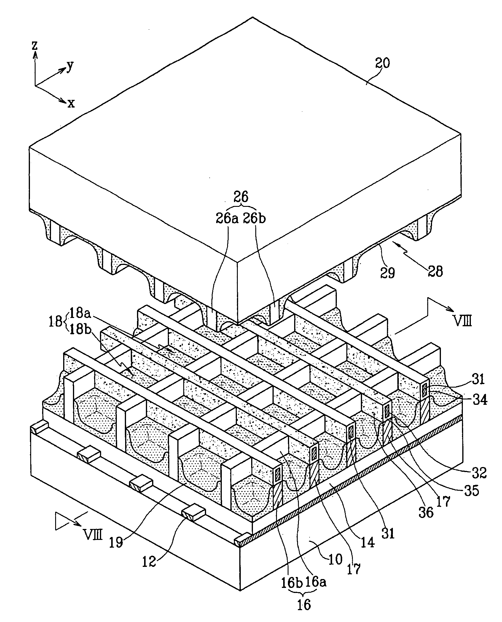
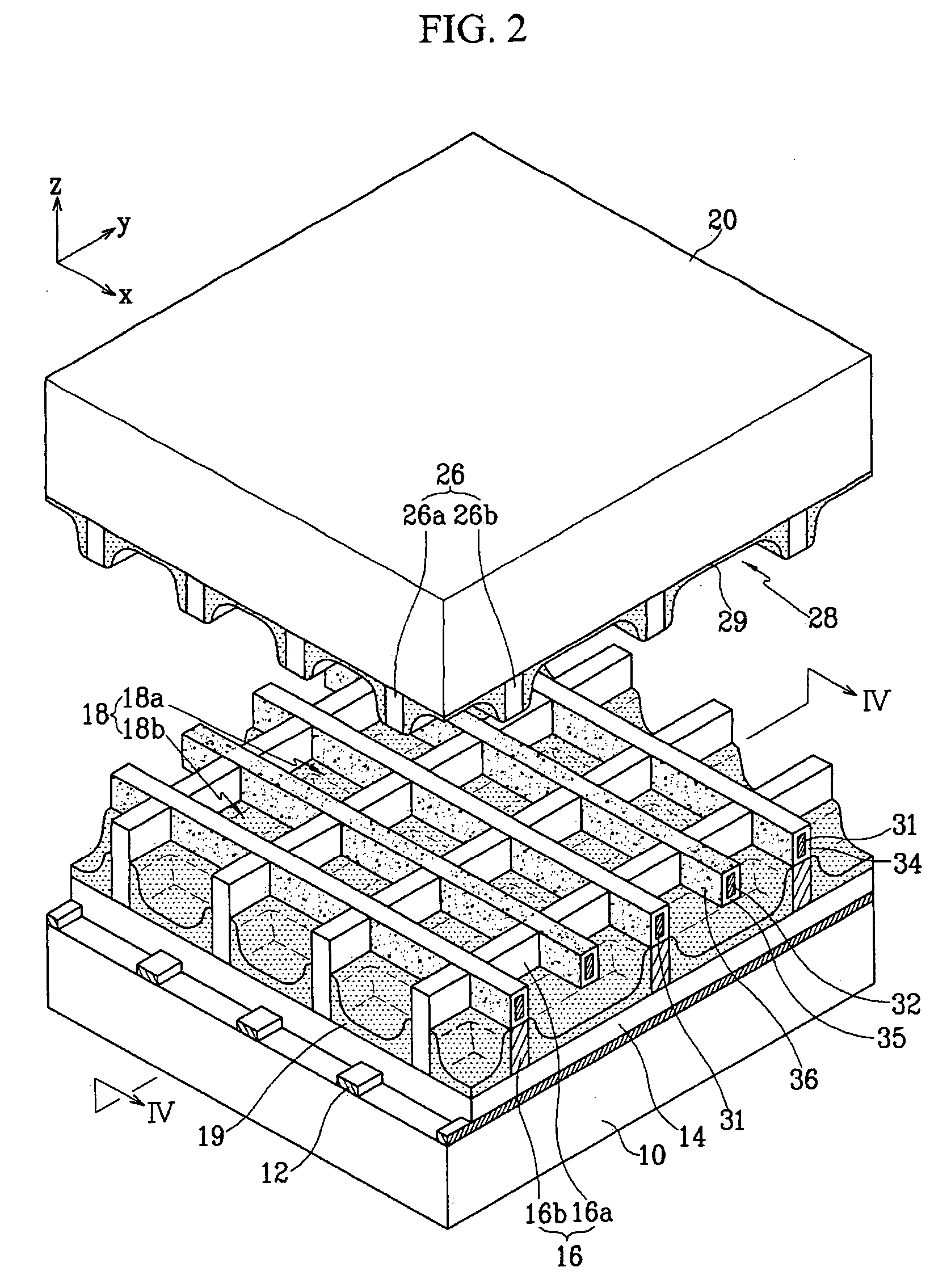
[0052] The PDP includes a first substrate 10 (hereinafter, referred to as a rear substrate) and a second substrate 20 (hereinafter, referred to as a front substrate). The rear and front substrates 10 and 20 face each other with a predetermined interval in between to provide for the discharge space. The discharge space is partitioned by barrier ribs 16 and 26 to define a plurality of discharge cells 18.
[0053] Phosphor layers 19 and 29 are located to coat sidewalls of the barrier ribs 16 and 26 and bottom surfaces of the discharge cells 18. The phosphor layers 19 and 29 absorb vacuum ultraviolet (VUV) light and emit visible light. The discharge cells 18 of the discharge space are filled with discharge gas, such as a mixture of Xe and Ne.
[0054] Address electrodes 12 are located parallel to each other on an inner surface of the rear substrate 10 and extend in a first direction (y-direction in the figure). A dielectric layer 14 is located on the inner surface of the rear substrate 10 t...
third embodiment
[0077] Referring to FIG. 8, in the third embodiment, transverse cross sections of the second electrodes 32 and the corresponding auxiliary barrier rib elements 17 have substantially the same central lines L. Therefore, each of the second electrodes 32 can be used to produce discharges in both regions 18a and 18b of the discharge cells 18.
[0078] The first electrodes 31, provided with the dielectric layer 34 and the MgO protective layer 36, are located between the second and fourth barrier rib elements 16b and 26b and extend parallel the second and the fourth barrier rib elements 16b and 26b. Similarly, the second electrodes 32, provided with the dielectric layer 35 and the MgO protective layer 36, are located between the auxiliary barrier rib elements 17 and the third barrier rib elements 26a and run in a direction parallel to the auxiliary barrier rib elements 17 and intersecting the third barrier rib elements 26a.
[0079] In order to make the second electrodes 32 and the auxiliary b...
fourth embodiment
[0081] Turning now to FIGS.9,10 and 11, FIG.9 is a partial exploded perspective view of a PDP according to the present invention, FIG. 10 is a schematic plan view of an electrode and discharge cell structure of the PDP of FIG. 9 and FIG. 11 is a partially cross-sectional view taken along line XI-XI of FIG. 9 of the assembled PDP.
[0082] Referring to FIGS. 9, 10 and 11, the structure of the PDP according to the fourth embodiment is similar to that of the PDP according to the third embodiment. The difference is that the first and second electrodes 314 and 324 have the protrusions 314a and 324a protruding toward the second and first electrodes 324 and 314 in the discharge cells 18, respectively. The protrusions can be formed on both the first and the second electrodes 314 and 324 or only on one of the first electrodes 314 and the second electrodes 324.
[0083] The protrusions 314a and 324a can be located at various locations along the direction perpendicular to the longitudinal direction...
PUM
 Abstract
Description
Claims
Application Information