High bandwidth high gain receiver equalizer

a receiver equalizer and high-gain technology, applied in the field of receiver circuits, can solve the problems of increasing the bit-error-rate (ber), increasing the degradation of the signal, and conventional equalizers do not have the bandwidth and gain that are required for today's applications, and achieve the effect of high bandwidth and high gain

Active Publication Date: 2006-01-05
TEXAS INSTR INC
View PDF9 Cites 23 Cited by
  • Summary
  • Abstract
  • Description
  • Claims
  • Application Information

AI Technical Summary

Problems solved by technology

Band-limiting produces a severe amount of inter-symbol interference (ISI), resulting in increased bit-error-rate (BER).
The higher the data rate is, the higher the degradation of the signal.
Conventional equalizers do not have a high enough bandwidth and gain that is required for today's applications.

Method used


Image

  • High bandwidth high gain receiver equalizer
  • High bandwidth high gain receiver equalizer
  • High bandwidth high gain receiver equalizer

Examples


Embodiment Construction

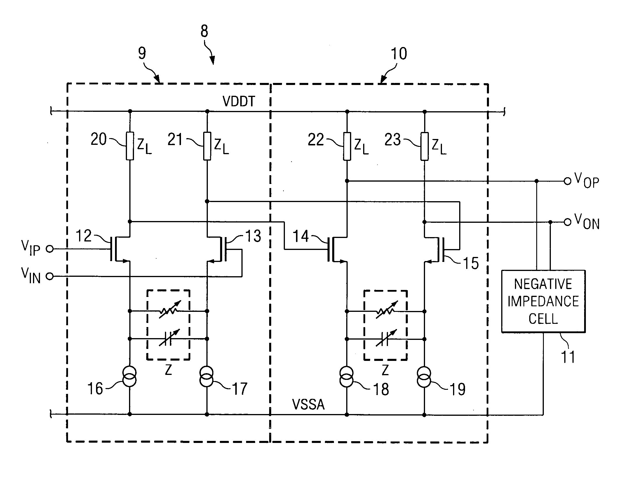
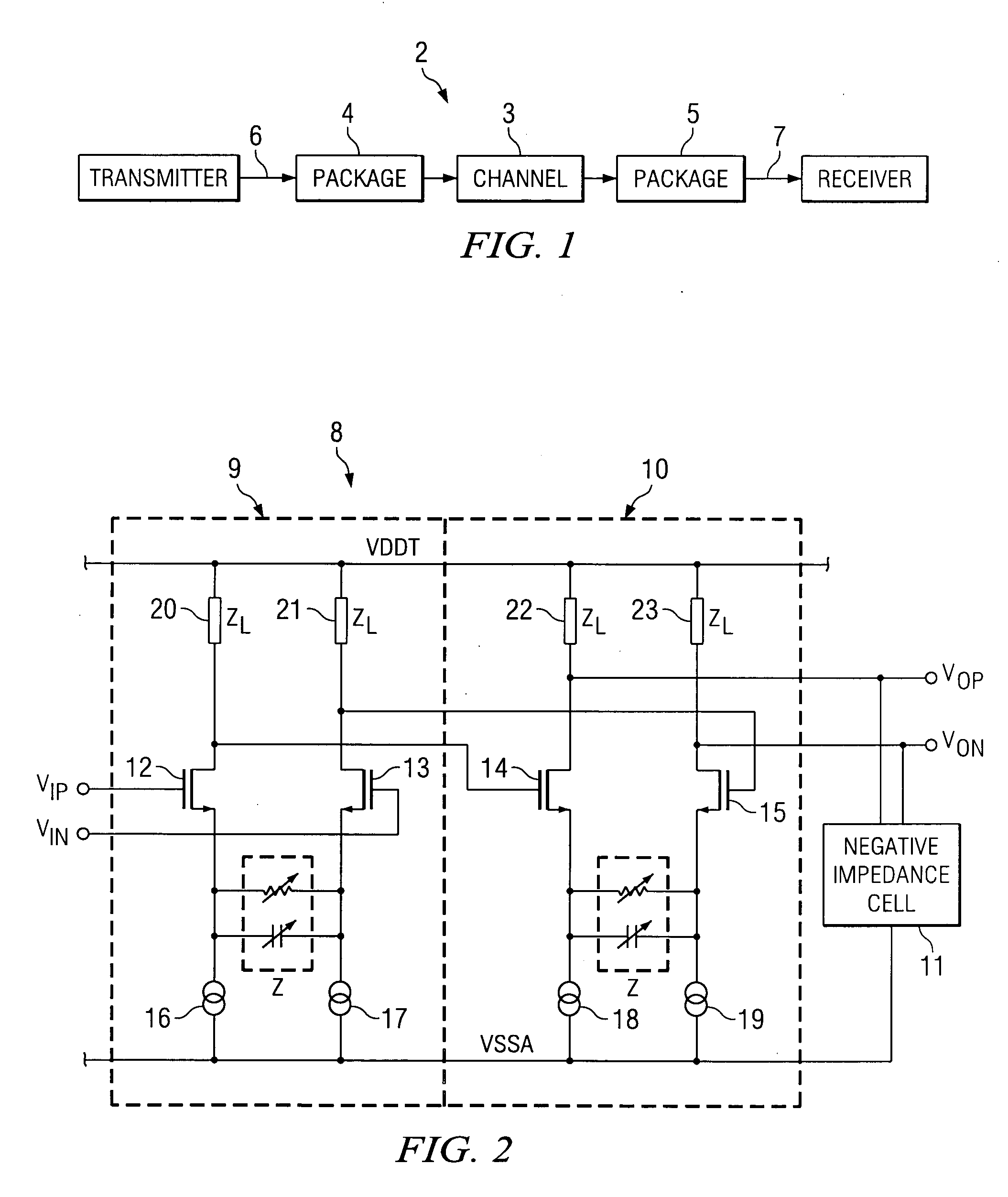
[0014] With reference to FIG. 2, a preferred embodiment of a receiver equalizer 8 is shown, and which comprises a pair of cascaded basic equalizer stages 9, 10 and a negative impedance cell 11 connected across the second of the equalizer stages 10. Each equalizer stage 9, 10 comprises two NMOS transistors 12, 13, 14, 15 arranged as a differential pair. Each transistor 12, 13, 14, 15 is connected to a current source 16, 17, 18, 19. Each equalizer stage 9, 10 has a degeneration impedance Z comprising a parallel RC circuit which connects the current sources 16, 17, 18, 19 of the differential pair of transistors 12, 13, 14, 15. Each of the equalizer stages 9, 10 also includes load impedances ZL 20, 21, 22, 23 connected between the transistors 12, 13, 14, 15 and the VDDT rail. The transistors 12, 13 of the first equalizer stage 9 have respective inputs VIP and VIN. The output of transistor 12 is connected to the input of transistor 14 of the second equalizer stage 10, and the output of t...


PUM


Abstract

There is provided a receiver equalizer comprising, a first equalizer unit having a basic equalizer stage and a negative impedance cell connected to said basic equalizer stage. Preferably the negative impedance cell comprises a pair of back to back transistors, and connected thereto a parallel resistor capacitor RC network. The basic equalizer stage comprises: a pair of current sources; a pair of transistors arranged as a differential pair, each transistor connected to a different one of the current sources; and a degeneration impedance connected in between the two current sources, and the transistors, wherein the negative impedance cell is connected across the outputs of the pair of transistors.

Description

FIELD OF THE INVENTION [0001] The present invention relates to receiver circuits, and more particularly, to a high bandwidth high gain receiver equalizer and a method of applying equalization at the receiver. BACKGROUND OF THE INVENTION [0002]FIG. 1 illustrates a typical transmitter / receiver channel link 2 in a communications system. The transmitted signal is band-limited by the channel 3, package traces 4, 5 and the load capacitances at the transmitter output 6, and the receiver input 7. Band-limiting produces a severe amount of inter-symbol interference (ISI), resulting in increased bit-error-rate (BER). The higher the data rate is, the higher the degradation of the signal. However, applying equalization at the receiver reduces ISI and improves the BER. Conventional equalizers do not have a high enough bandwidth and gain that is required for today's applications. Thus there is a need for an improved receiver equalizer. [0003] The present invention aims to mitigate at least one of ...

Claims


Application Information

Patent Timeline
Patent Type & Authority Applications(United States)
IPC IPC(8): H03H11/00H03F1/42H03H11/12H03H11/44H04L25/03
CPCH04L25/03878H03H11/1291H03F1/42H03H11/44H04L25/03828
Inventor SINGH, BHAJANPICKERING, ANDREWWARD, RICHARD
Owner TEXAS INSTR INC
Why Eureka
Try Eureka