
Apparatus and method for monitoring the output of a warning or indicator light

a technology of warning or indicator light and apparatus, which is applied in the direction of optical radiation measurement, fire alarm radiation actuation, instruments, etc., can solve the problems of reducing the availability of photo sensors, affecting the accuracy of sensor output, and saturation of photo sensors, so as to increase the signal strength

Active Publication Date: 2006-01-05
GENERAL ELECTRIC CO
View PDF7 Cites 45 Cited by
  • Summary
  • Abstract
  • Description
  • Claims
  • Application Information

AI Technical Summary

Benefits of technology

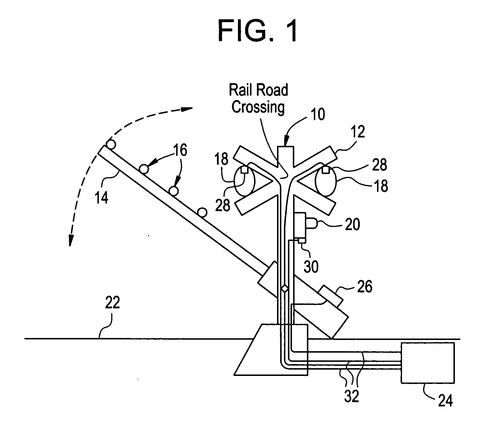
[0012] A warning light for a railroad crossing, comprising: a housing for a light emitting device; a roundel secured to the housing, the roundel being positioned in front of the light emitting device to provide an illuminated surface of the warning light; a shroud extending from the housing and the roundel; a sensor secured to the shroud and being positioned to detect light from the illuminated surface wherein the sensor is configured to provide an operational status signal of the warning light, the sensor comprising; a photodiode configured to generate a signal correspondin

Problems solved by technology

Such equipment must necessarily be located throughout the railroad system, and is thus geographically dispersed and often located at places that are difficult to access.
However, the location of the sensor or photo sensor may cause the sensor to be exposed to environmental conditions that may affect the accuracy of the sensor output.
Furthermore, and in order to not block the light output while also measuring the same the sensor may be positioned such that it will detect a non-uniform light signal (e.g., the sensor is not centrally located with respect to the light).
This reflected sunlight may lead to saturation of the photo sensor.
Saturation would preclude the quantification of flashing light output irradiance and reduce the availability of the photo sensor.

Method used


Image

  • Apparatus and method for monitoring the output of a warning or indicator light
  • Apparatus and method for monitoring the output of a warning or indicator light
  • Apparatus and method for monitoring the output of a warning or indicator light

Examples


Embodiment Construction

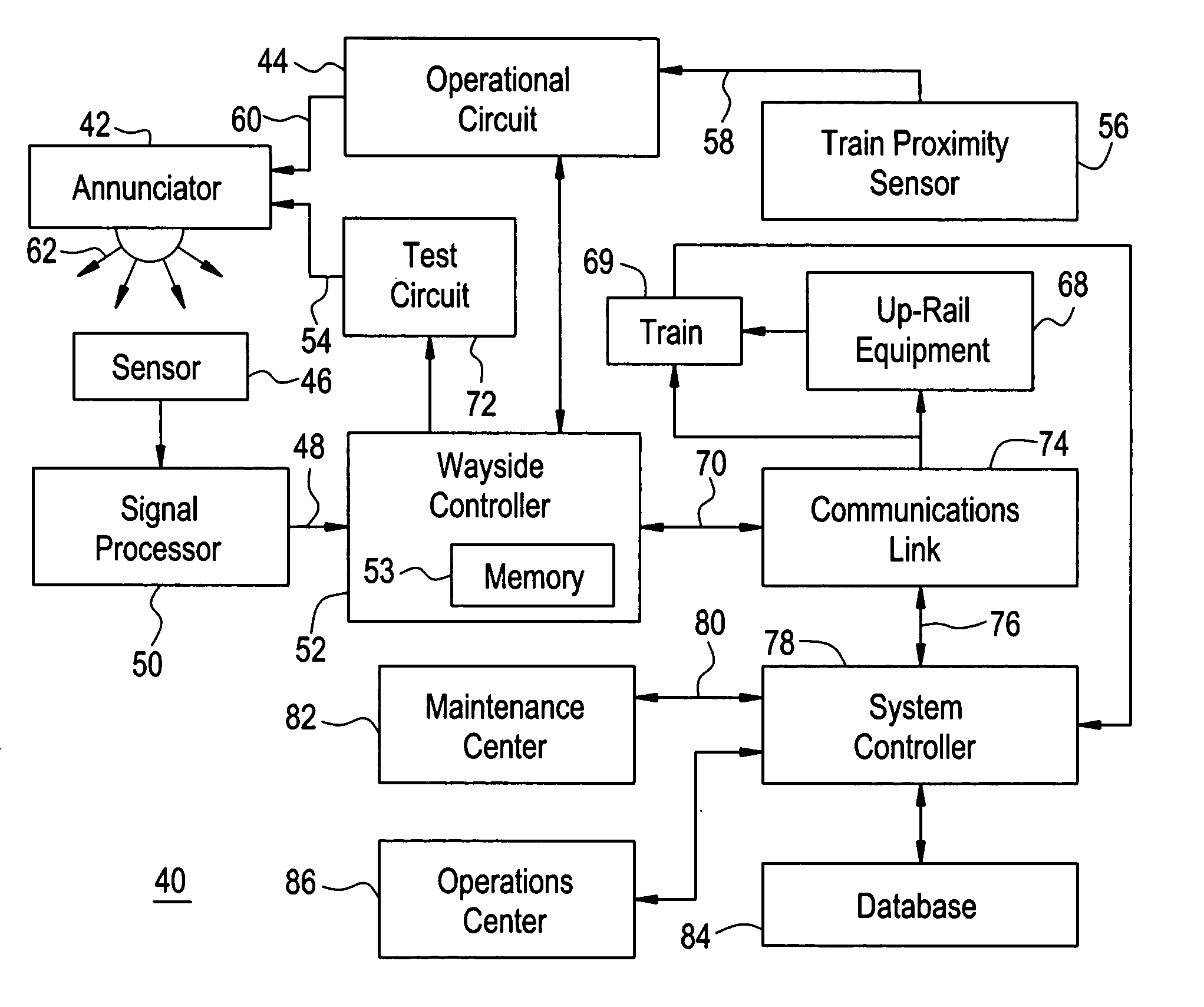
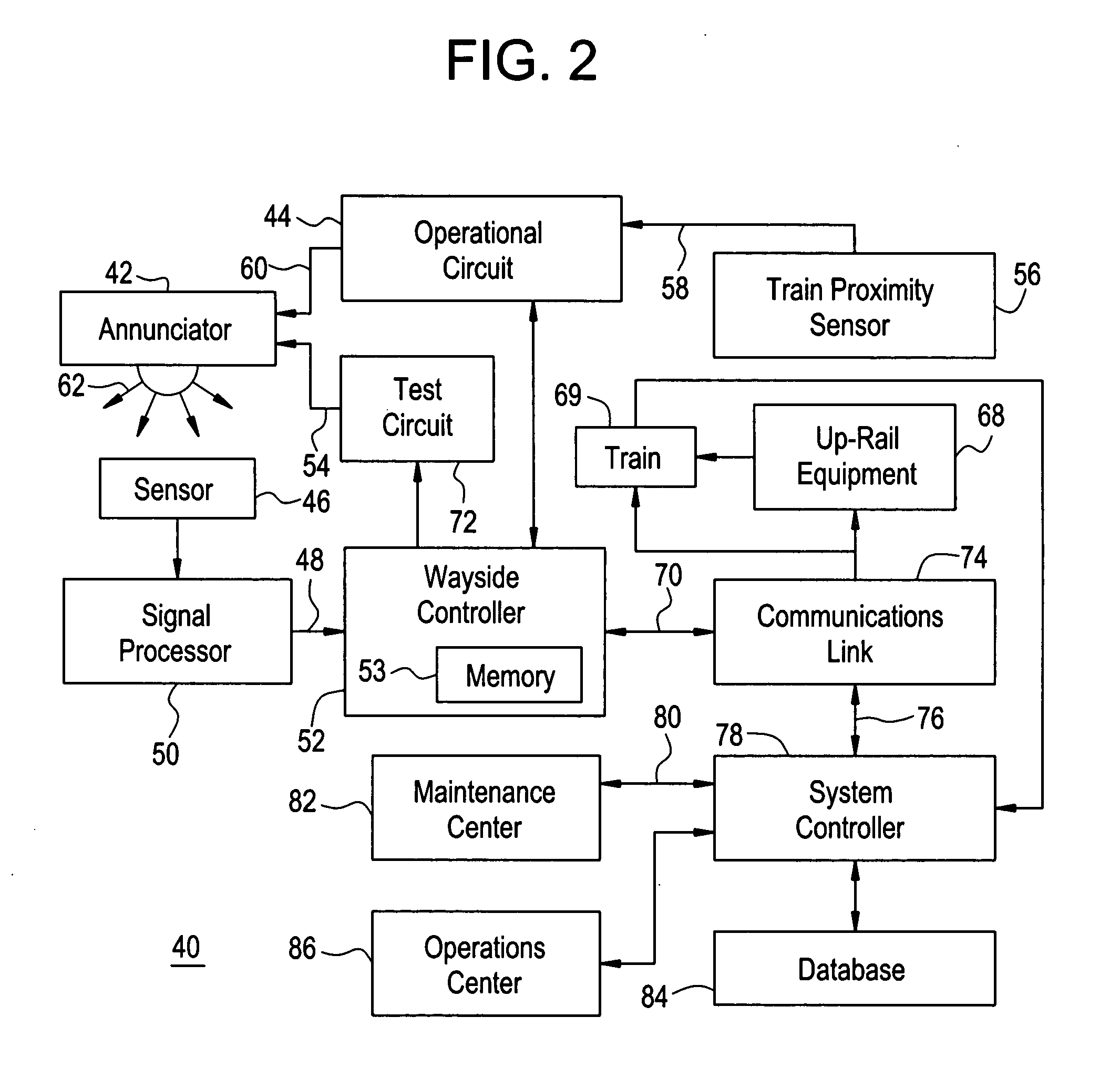
[0035] Disclosed herein is an operational status detection system for a railroad warning device having a warning light. The system will remotely provide a signal indicative of the operational status of the warning light. The system includes a photodiode configured to generate a signal corresponding to light output of the warning light of the railroad warning device when the device is activated. The signal is filtered to only allow portions of the signal corresponding to the light output of the warning light to be presented as an output signal of the warning light. More specifically, and in accordance with exemplary embodiments, the ambient sunlight that may be received by the photodiode is filtered out from the signal. The filtered signal is then received by a microcontroller which compares the output signal to a pair of threshold values corresponding to a range of an acceptable light output of the warning light. In this fashion, the system will be able to detect possible failure mo...


PUM


Abstract

An operational status detection system for a railroad warning device having a warning light, comprising: a photodiode configured to generate a signal corresponding to a light output of the warning light of the railroad warning device; an amplifier for increasing a signal strength of the signal and providing an output corresponding to the signal; a filter for receiving the output, the filter being configured to only allow portions of the output corresponding to the light output of the warning light to be presented as an output signal of the warning light; and a microcontroller receptive to the output signal and for comparing the output signal to a threshold value, the threshold value corresponding to an acceptable light output of the warning light.

Description

BACKGROUND [0001] This invention relates generally to railroad crossing and wayside signals, and more particularly a method and apparatus for monitoring the operational status of the railroad crossing signal. [0002] Railroad systems include wayside equipment such as switches, signals, and vehicle detectors including hot wheel detectors, dragging equipment detectors, high / wide load detectors, vehicle identification systems, etc. Such equipment must necessarily be located throughout the railroad system, and is thus geographically dispersed and often located at places that are difficult to access. Systems are currently in use for communicating operational and status information relating to the condition of the train or the track to control centers through various types of modems. For example, position indicators are provided on switches and a signal responsive to the position of a switch is communicated to a control center for that section of track. [0003] Grade crossings where streets...

Claims


Application Information

Patent Timeline
IPC IPC(8): G08B21/00G08B17/12G08G1/095B61L5/12G01J1/32
CPCB61L5/1881B61L29/30G08G1/095G08B5/36G08B29/10G01J1/18
Inventor DAVENPORT, DAVIDSTEVENS, DANIELUTTERBACK, STEPHEN DAVID
Owner GENERAL ELECTRIC CO
Learn More