Apparatus and method of charge sharing in LCD

a technology of apparatus and charge sharing, applied in the direction of static indicating devices, instruments, etc., can solve the problems of power consumption, higher power consumption, and power consumption, and achieve the effect of reducing power consumption

Active Publication Date: 2006-01-05
HIMAX TECH LTD
View PDF2 Cites 40 Cited by
  • Summary
  • Abstract
  • Description
  • Claims
  • Application Information

AI Technical Summary

Benefits of technology

[0007] The object of the present invention is to provide an apparatus and method for charge sharing in an LCD,

Problems solved by technology

In general, a conventional TFT-LCD is operated by providing positive and negative video signals alternately to the liquid crystal on the basis of VCOM, however, resulting in flicker.
When convert the video signal's polarity from positive to negative or fr

Method used


Image

  • Apparatus and method of charge sharing in LCD
  • Apparatus and method of charge sharing in LCD
  • Apparatus and method of charge sharing in LCD

Examples


Embodiment Construction

[0019]FIG. 3 illustrate the video signal's polarity conversion with charge sharing in a TFT-LCD. In FIG. 3, the video signal of two adjacent source line DL#1 and DL#2 convert polarity with charge sharing during asserted period of control signal TP. The video signal of source line DL#1 and DL#2 are applied charge sharing and the voltage levels of the source line DL#1 and DL#2 both becomes a common voltage level, an average voltage level of the source line DL#1 and DL#2. The video signal of source line DL#1 is converted from positive polarity to negative polarity through the common voltage level, the video signal of source line DL#2 is converted from negative polarity to positive polarity through the common voltage level. Only the voltage range from the common voltage level to negative polarity of source line DL#1 and the voltage range from the common voltage level to positive polarity of source line DL#2 are needed to be driven. Because of smaller range of voltage level change, lower...


PUM


Abstract

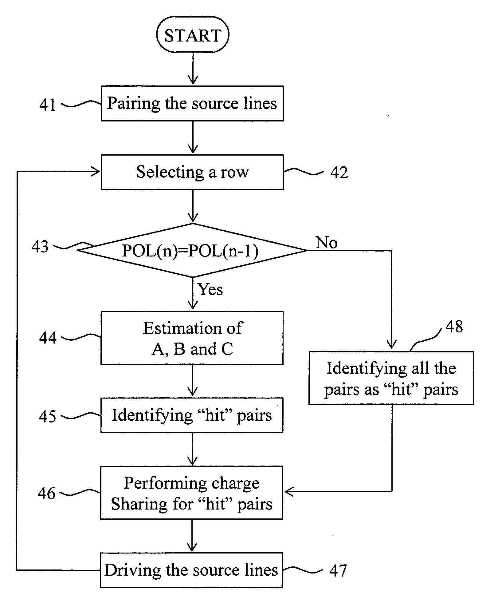
A method for charge sharing between source lines of a pixel array. The method includes the steps of grouping the source lines into pairs, implementing charge sharing if data polarities of a currently and a last scanned row are different; otherwise, in each pair of the source lines, estimating a first and second energy driving the two source lines respectively with and without a preliminary charge sharing, and implementing charge sharing only if the first energy is smaller than the second energy.

Description

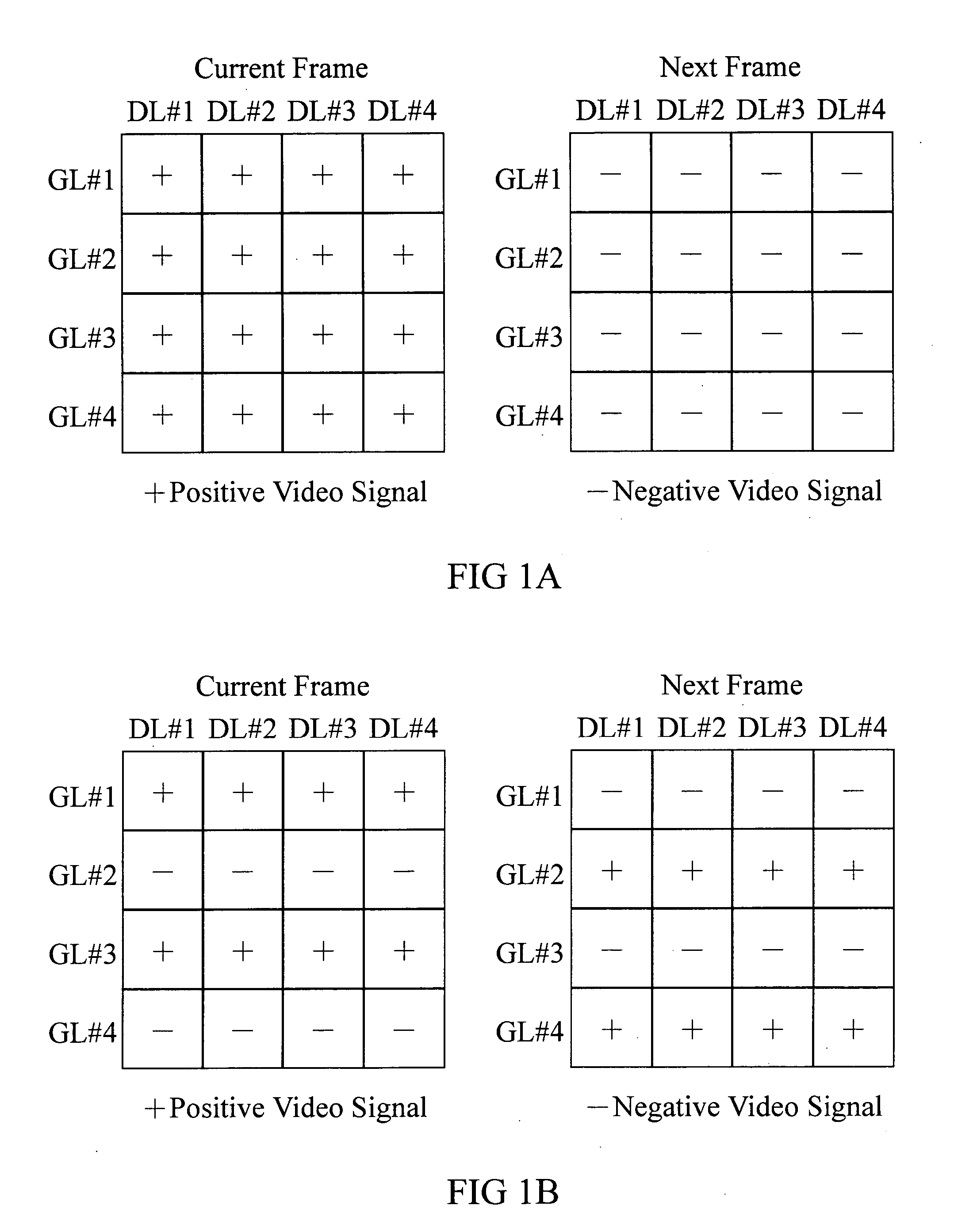
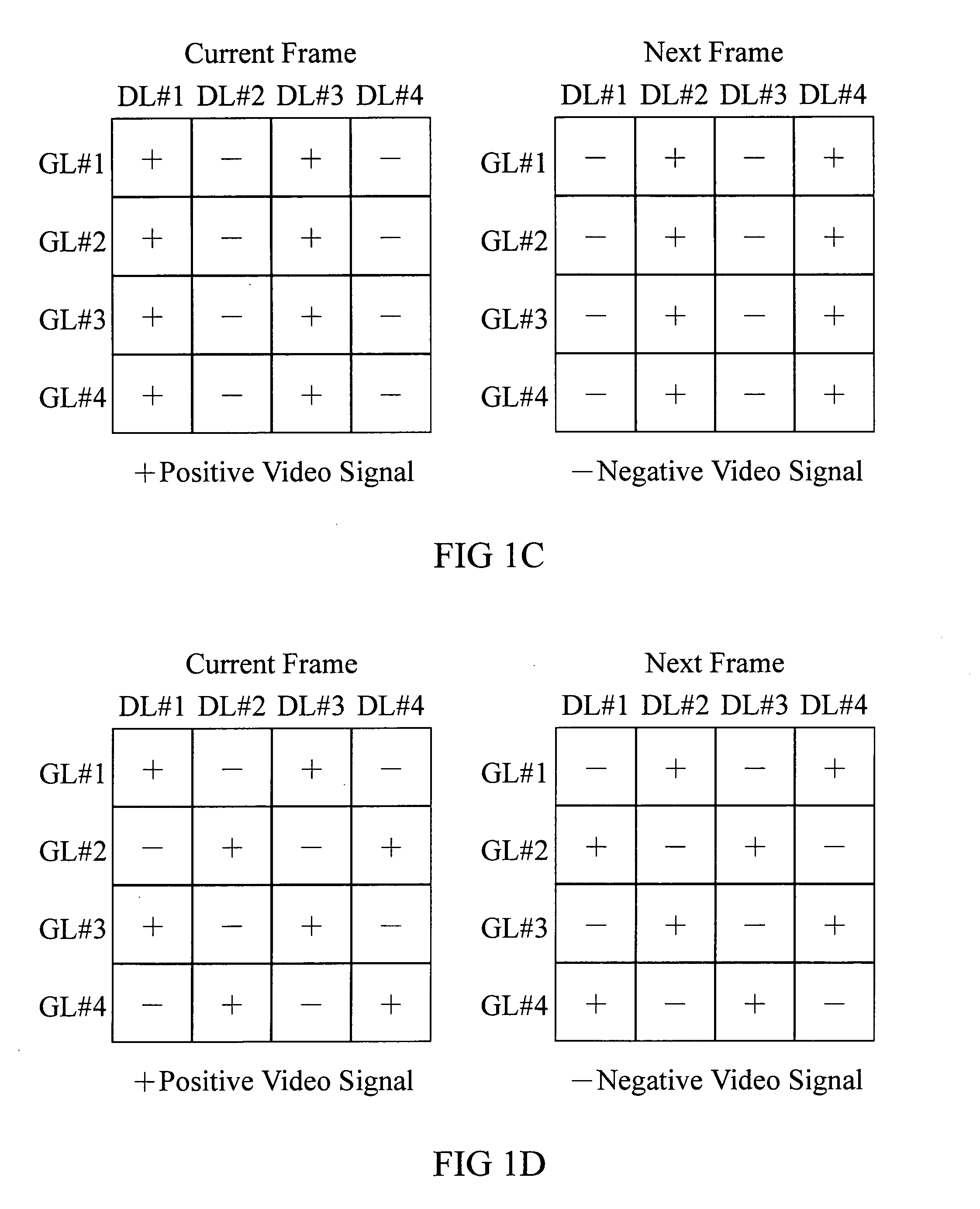
BACKGROUND OF THE INVENTION [0001] 1. Field of the Invention [0002] The present invention relates to driving an LCD and particularly to an apparatus and method for charge sharing between source lines of the pixel array in a TFT-LCD. [0003] 2. Description of the Related Art [0004] In general, a conventional TFT-LCD is operated by providing positive and negative video signals alternately to the liquid crystal on the basis of VCOM, however, resulting in flicker. To reduce the generation of flicker, a conventional TFT-LCD is employed one of a frame inversion, line inversion, column inversion and dot inversion shown in FIGS. 1A to 1D, respectively. [0005] The frame inversion of FIG. 1A is a mode that the polarity of the video signal changed only when the frame is changed. The line inversion of FIG. 1B is a mode that the video signal's polarity is varied whenever the gate line GL changes. The column inversion shown in FIG. 1C converts the polarity of the video signal whenever the source l...

Claims


Application Information

Patent Timeline
IPC IPC(8): G09G3/36
CPCG09G3/3614G09G2330/023G09G3/3688
Inventor CHEN, MING-YEONGTSAI, PO-HSIEN
Owner HIMAX TECH LTD
Why Eureka
Try Eureka