Advanced MIMO interleaving

Active Publication Date: 2006-01-05
QUALCOMM INC
View PDF3 Cites 38 Cited by
  • Summary
  • Abstract
  • Description
  • Claims
  • Application Information

AI Technical Summary

Benefits of technology

[0013] An improved interleaver is provided as set forth herein. In one aspect, enhanced interleaving gain is provided with the improved interleaver. The improved gain can result from increasing distances between adjacent bits or next adjacent bits,

Problems solved by technology

Because wireless networks are expected to operate in unfavorable conditions, such as in the presence of reflections, interference, movement of receivers/transmitters, etc., much effort is needed to correctly transmit and receive data over a wireless channel.
Of course, where there are unrecoverable errors, there is

Method used


Image

  • Advanced MIMO interleaving
  • Advanced MIMO interleaving
  • Advanced MIMO interleaving

Examples


Example

Example Implementation Details

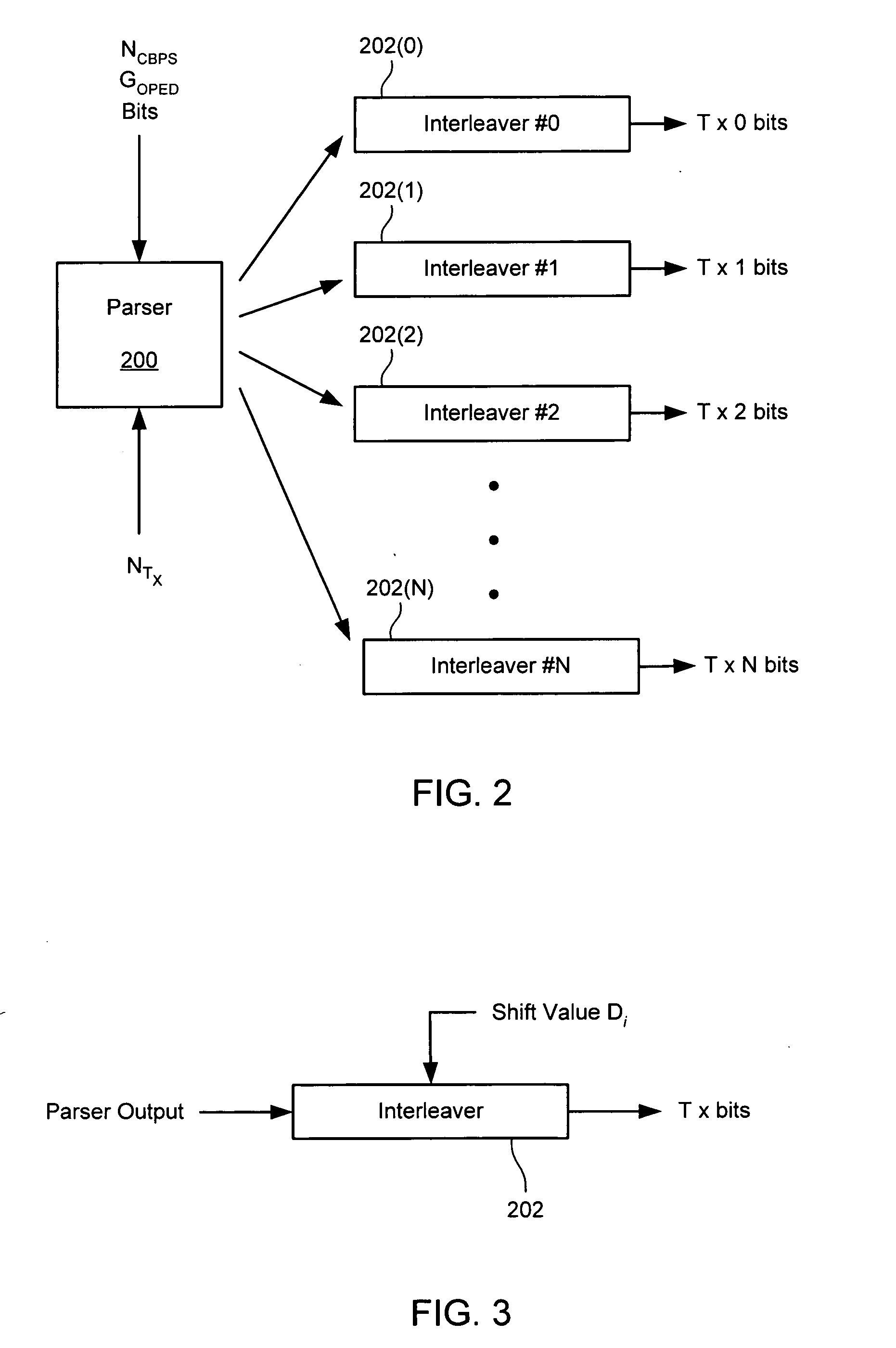
[0066]FIG. 2 illustrates an example implementation of a MIMO interleaving system. As shown, the input bit stream from an encoder is parsed by parser 200 to a plurality of stream interleavers 202. The parser might be provided with the number of spatial streams and parse bits on a round-robin basis. Other parsings might be used instead, such as parsing more generally using another parsing function. The parsing function for the examples above is kn=NTX*k+n (i.e., round-robin with one bit per spatial stream, then on to the next spatial stream), but a more general function f(k,n) might be used instead. For example, sending two bits to a spatial stream, then moving to the next spatial stream.

[0067]FIG. 3 illustrates an example of a stream interleaver 202 as might be used in the apparatus shown in FIG. 2. In this example, each stream interleaver 202 might be the same, but with different shift values Di. Thus, a four-transmitter MIMO system might use four of...


PUM


Abstract

A MIMO transmitter including an interleaving system for parsing encoded bits to a plurality of spatial streams and a plurality of interleavers to interleave bits for spatial streams such that at least a first spatial stream uses a first stream interleaver that interleaves with a pattern distinct from a second stream interleaver interleaving for a second spatial stream.

Description

CROSS-REFERENCE TO RELATED APPLICATIONS [0001] This application claims priority from U.S. Provisional Patent Application Nos. 60 / 585,246 filed Jul. 1, 2004 entitled MIMO INTERLEAVING, 60 / 589,390 filed Jul. 19, 2004 entitled ADVANCED MIMO INTERLEAVING, and 60 / 600,962 filed Aug. 11, 2004 entitled ADVANCED MIMO INTERLEAVING, which are hereby incorporated by reference, as if set forth in full in this document, for all purposes.BACKGROUND OF THE INVENTION [0002] Wireless networks have become increasingly popular, as computers and other devices can be coupled for data communications without requiring wired connections between the network nodes. Because wireless networks are expected to operate in unfavorable conditions, such as in the presence of reflections, interference, movement of receivers / transmitters, etc., much effort is needed to correctly transmit and receive data over a wireless channel. [0003] A typical node in a wireless network (referred to in the standards as a “station”) i...

Claims


Application Information

Patent Timeline
IPC IPC(8): H04L27/28
CPCH03M13/2757H04B7/04H04L1/0041H04L27/2602H04L1/06H04L1/0656H04L27/2601H04L1/0071H04B7/0413
Inventor VAN NEE, D.J. RICHARD
Owner QUALCOMM INC
Why Eureka
Try Eureka