Control device for vehicular drive system

a control device and drive system technology, applied in hybrid vehicles, electric propulsion mountings, jet propulsion mountings, etc., can solve the problems of unfavorable drive system size, unfavorable drive system operation, so as to reduce the operating shock of the drive system and improve the fuel economy of the vehicle.

Active Publication Date: 2006-01-05
TOYOTA JIDOSHA KK
View PDF4 Cites 34 Cited by
  • Summary
  • Abstract
  • Description
  • Claims
  • Application Information

AI Technical Summary

Benefits of technology

[0008] The present invention was made in view of the background art described above. It is therefore an object of the present invention to provide a control device for a vehicular drive system, which enables the vehicular drive system to be small-sized and which permits an improvement of the fuel economy of the vehicle and reduction of the operating shock of the drive system.

Problems solved by technology

However, there is not known any power transmitting mechanism that is suitable for improving both of the fuel economy and the power transmitting efficiency.
This drive system requires the first electric motor to be large-sized with an increase of the required output of the engine, so that the second electric motor operated with the electric energy supplied from the first electric motor is also required to be large-sized, whereby the drive system tends to be unfavorably large-sized.
The same drive system also suffers from a risk of deterioration of the fuel economy during a high-speed running of the vehicle, for example, due to conversion of a portion of the mechanical energy produced by the engine into an electric energy, which is subsequently converted into a mechanical energy to be transmitted to the drive wheels of the vehicle.
A similar problem is encountered in a vehicular drive system wherein the differential mechanism is used as a transmission the speed ratio of which is electrically variable, for instance, as a continuously variable transmission which is a so-called “electrically controlled CVT”.

Method used


Image

  • Control device for vehicular drive system
  • Control device for vehicular drive system
  • Control device for vehicular drive system

Examples


first embodiment

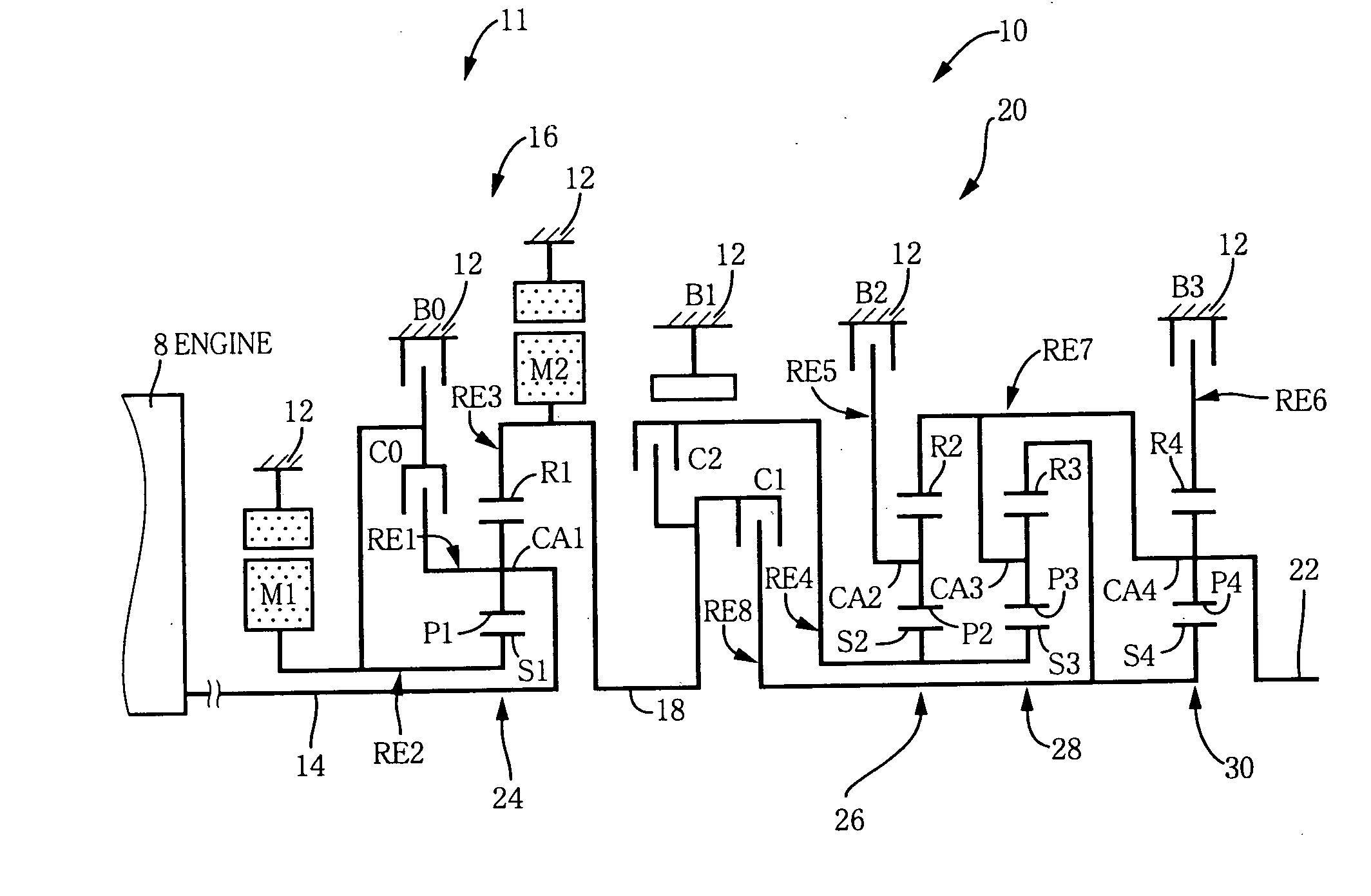
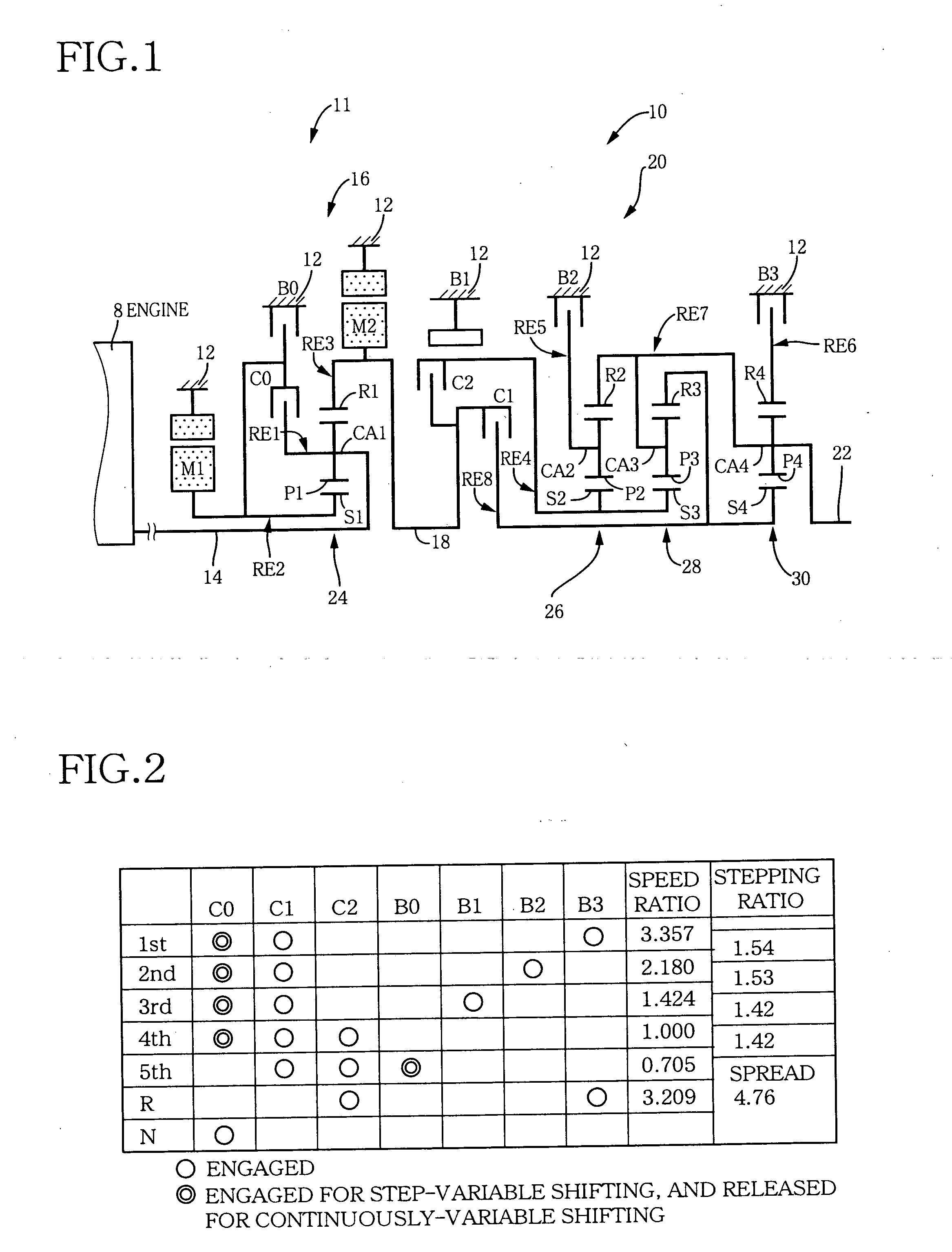
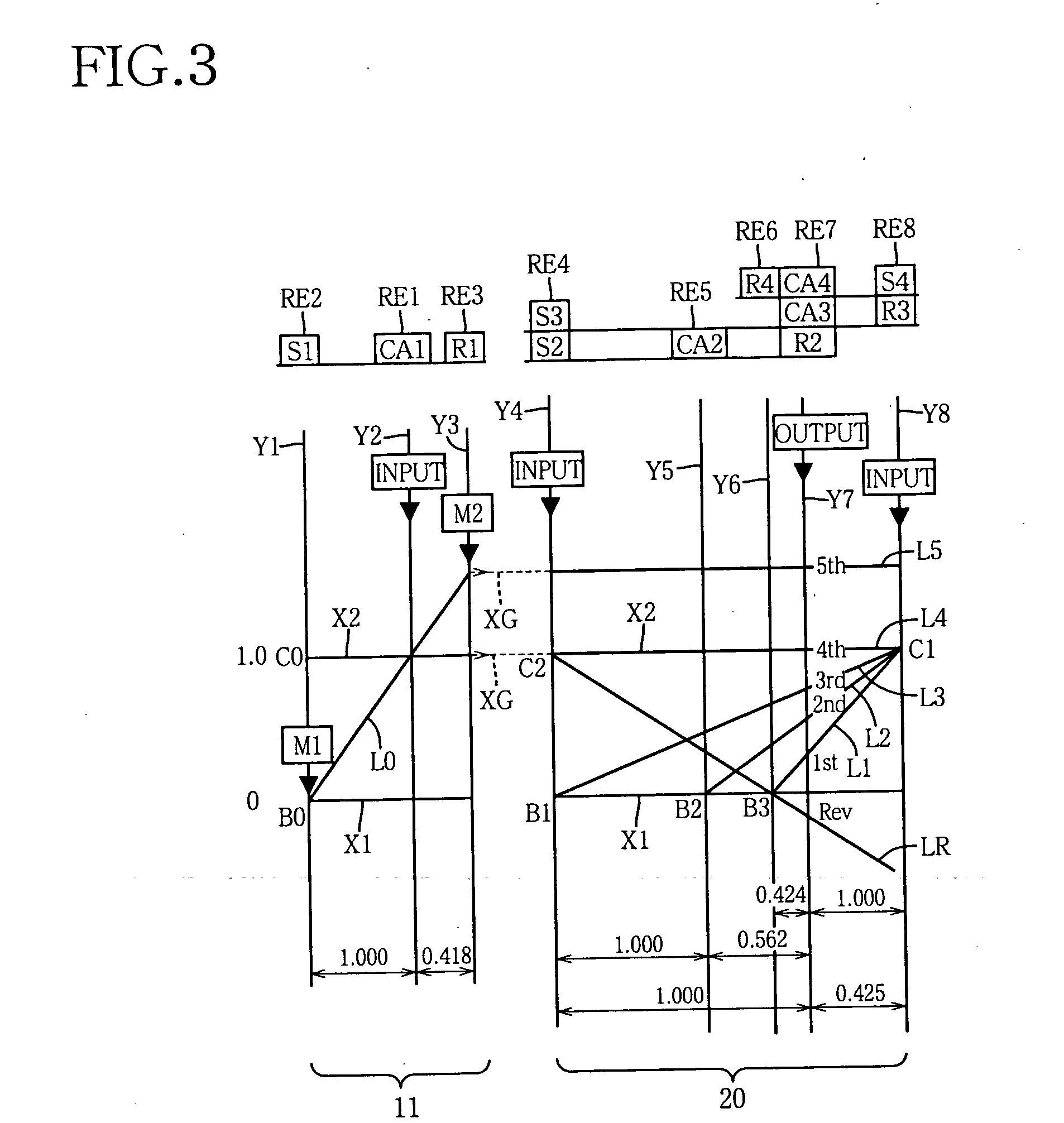
[0059]FIG. 1 is a schematic view explaining a transmission mechanism 10 constituting a part of a drive system for a hybrid vehicle, which drive system is controlled by a control device according to one embodiment of this invention. The transmission mechanism 10 includes: an input rotary member in the form of an input shaft 14 disposed on a common axis in a transmission casing 12 functioning as a stationary member attached to a body of the vehicle; a continuously-variable transmission portion 11 connected to the input shaft 14 either directly, or indirectly via a pulsation absorbing damper (vibration damping device) not shown; a step-variable or multiple-step automatic transmission portion 20 interposed between and connected in series via a power transmitting member 18 (power transmitting shaft) to the continuously-variable transmission portion 11 and drive wheels 38 (shown in FIG. 5) of the vehicle; and an output rotary member in the form of an output shaft 22 connected to the autom...

second embodiment

[0117] Referring to the block diagram of FIG. 12, there is shown a control device according to a second embodiment of this invention, which is arranged to execute a switching-shock reducing routine illustrated in the flow chart of FIG. 13. While this control device according to the second embodiment is arranged to control the drive system including the engine 8 and the transmission mechanism 10 as shown in FIGS. 1 and 5, the control device includes a torque-reduction control portion 86 and an engagement-terminal-phase determining portion 88, in place of the power-source torque-change restriction control portion 82 provided in the first embodiment.

[0118] The engagement-terminal-phase determining portion 88 is arranged to determine whether the switching clutch C0 or brake B0 to be engaged to establish the step-variable shifting state is in a terminal phase of its engaging action, which is initiated when the switching control portion 50 has determined that the transmission mechanism 1...

third embodiment

[0142] Referring to the schematic view of FIG. 15, there is shown an arrangement of a transmission mechanism 70 of a vehicular drive system according to a third embodiment of this invention, which may be controlled by the electronic control device in the first or second embodiment. Although the transmission mechanism 70 is different from the transmission mechanism 10 according to the first embodiment of FIGS. 1-11, the transmission mechanism 70 is controlled by an electronic control device which is substantially identical with the electronic control unit 40 described above with respect to the first embodiment of FIGS. 1-11 or the second embodiment of FIGS. 12-14. FIG. 16 is a table indicating gear positions of the transmission mechanism 70, and different combinations of engaged states of the hydraulically operated frictional coupling devices for respectively establishing those gear positions, while FIG. 17 is a collinear chart for explaining a shifting operation of the transmission ...


PUM


Abstract

A control device for a vehicular drive system including (a) a differential mechanism operable to distribute an output of an engine to a first electric motor and a power transmitting member, and (b) a second electric motor disposed between the power transmitting member and a drive wheel of a vehicle, and a differential-state switching device operable to place the differential mechanism selectively in one of a differential state and a locked or non-differential state, the control device including a switching control portion operable to control the differential-state switching device to place the differential mechanism selectively in one of the differential and locked states, and a power-source torque-change restriction control portion operable to restrict a change of an output torque of the engine upon switching of the differential mechanism between the differential and locked states, or a torque-reduction control portion operable to reduce at least one of output torques of an engine and first and second electric motors, upon switching of the differential mechanism from the differential state to the locked state, or to reduce an inertial torque generated due to a speed change of the differential mechanism upon switching of the differential mechanism from the differential state to the locked state.

Description

[0001] The present application is based on Japanese Patent Application Nos. 2004-196081 and 2004-203946 filed on Jul. 1 and Jul. 9, 2004, respectively, the content of which is incorporated herein by reference. BACKGROUND OF THE INVENTION [0002] 1. Field of the Invention [0003] The present invention relates in general to a vehicular drive system including a differential mechanism which has a differential function and functions as a transmission mechanism, and more particularly to techniques for reducing the size of electric motors provided in the vehicular drive system. [0004] 2. Description of Related Art [0005] There is known a drive system for a vehicle, which includes a differential mechanism arranged to distribute an output of an engine to a first electric motor and an output shaft, and a second electric motor disposed between the output shaft of the differential mechanism and drive wheels of the vehicle. Examples of this type of vehicular drive system include drive systems for ...

Claims


Application Information

Patent Timeline
Patent Type & Authority Applications(United States)
IPC IPC(8): B60K5/08B60L50/11
CPCB60K6/445B60W10/06B60W10/08B60W10/10Y10T477/20Y02T10/6286Y10S903/93Y02T10/6239Y10T477/23B60W20/00Y02T10/62B60W20/10
Inventor TABATA, ATSUSHITAGA, YUTAKA
Owner TOYOTA JIDOSHA KK
Why Eureka
Try Eureka