Time delay estimation method and system for use in ultrasound imaging

a time delay and ultrasound imaging technology, applied in the field of imaging systems, can solve the problems of degrading the focusing of the transmission and receive, affecting the accuracy of the estimation method, and the loss of image resolution and contrast, so as to minimize the cost and size of the system, accurate estimation of time delays

Inactive Publication Date: 2006-01-05
GENERAL ELECTRIC CO
View PDF12 Cites 24 Cited by
  • Summary
  • Abstract
  • Description
  • Claims
  • Application Information

AI Technical Summary

Benefits of technology

[0013] Therefore there is a need for a method and system in ultrasound systems to accurately estimate time delays while minimizing the cost and size of the system.

Problems solved by technology

When this assumption fails, the transmit and receive focusing is degraded and there will be a loss of image resolution and contrast.
If the assumption is not correct, the delayed receive signals will not be well-aligned in time; the arrival time errors will be large.
Beamforming time delay errors typically introduce artifacts into the image which may lead to incorrect diagnosis or a longer examination time.
One problem with the above method is the requirement for converting both real signals to complex form.
Converting signals to their baseband form requires large and expensive filters.
Since this method requires converting each receive signal to its baseband form, it is undesirably costly.
In practice, such a region of uniform scatterers is not always available.
As a result, the time-delay estimates can be corrupted, especially when there are strongly reflecting scatterers which are not aligned with the desired scan direction.
If such a signal were used to estimate the time delay error, then correcting the observed arrival time errors would erroneously steer the beamformer toward the scatterer.

Method used


Image

  • Time delay estimation method and system for use in ultrasound imaging
  • Time delay estimation method and system for use in ultrasound imaging
  • Time delay estimation method and system for use in ultrasound imaging

Examples


Embodiment Construction

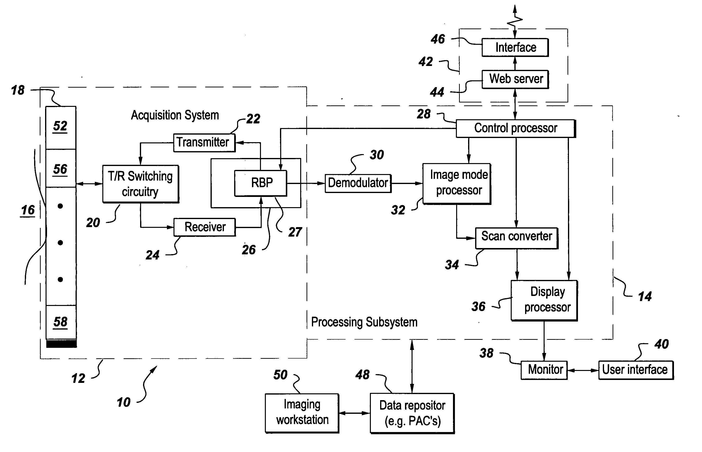
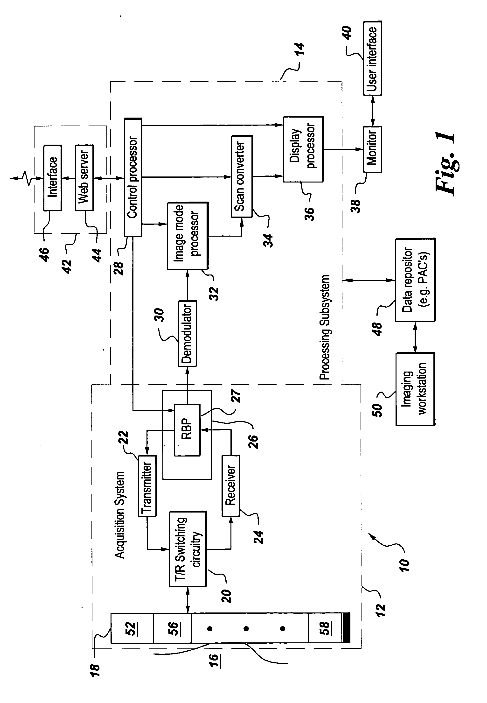
[0023]FIG. 1 is a block diagram of an embodiment of an ultrasound system 10 implemented in accordance to one aspect of the invention. The ultrasound system comprises of acquisition subsystem 12 and processing subsystem 14. The acquisition subsystem 12 comprises a transducer array 18 (comprising a plurality of transducer array elements), transmit / receive switching circuitry 20, a transmitter 22, a receiver 24, and a beamformer 26. Beamformer 26 includes a receive beamformer processor (RBP) 27. Processing subsystem 14 comprises a control processor 28, a demodulator 30, an imaging mode processor 32, a scan converter 34 and a display processor 36. The display processor is further coupled to a monitor for displaying images. User interface 40 interacts with the control processor and the display monitor. The processing subsystem may also be coupled to a remote connectivity subsystem 42 comprising a web server 44 and a remote connectivity interface 46. Processing subsystem may be further co...


PUM


Abstract

A method for correcting a time delay between at least two signals in ultrasound systems is provided. The ultrasound system comprises a beamformer processor comprising a summer coupled to the transducer array and configured for performing a complex operation on a first plurality of receive signals to generate a beamsum signal; wherein each of the receive signals comprise a corresponding beamforming delay and a complex filter coupled to the summer and configured to transform the beamsum signal to an analytical signal. The beamformer processor further comprises a plurality of correlator processors coupled to at least one respective transducer element and the complex filter, each correlator processor configured to calculate a correlation sum for at least one receive signal and at least one time delay estimator adapted to receive the correlation sum of at least one receive signal and configured to estimate the corresponding time delay using the correlation sum.

Description

BACKGROUND [0001] The invention relates generally to imaging systems and more specifically to a method and system for estimating and correcting time delays in an ultrasound imaging system. [0002] Ultrasound systems comprise an array of transducer elements used for transmitting a set of waveforms into an imaging subject and for receiving a set of reflected ultrasound signals. Each waveform is emitted with a relative time delay chosen to focus the net transmitted waveform in a desired direction and depth and with a desired shape. Similarly each received signal is individually delayed to maximize the response of the system to reflected energy for a desired direction and depth and with a desired shape. The delayed receive signals are summed and processed to create and display an image of the imaging subject. [0003] The transmit and receive time delays, known collectively as beamforming time delays, are typically calculated assuming that sound propagates through the body with a known, co...

Claims


Application Information

Patent Timeline
Patent Type & Authority Applications(United States)
IPC IPC(8): A61B8/00
CPCG01S7/52025G10K11/346G01S7/5205A61B8/00
Inventor RIGBY, KENNETH WAYNEMILLER, STEVEN CHARLES
Owner GENERAL ELECTRIC CO
Why Eureka
Try Eureka