Methods and apparatuses for bone restoration

a bone restoration and apparatus technology, applied in the field of surgical implants, can solve the problems of balloon withdrawal from the patient's body, numerous manipulations, kyphoplasty methods, etc., and achieve the effect of increasing the contact or support surfa

Active Publication Date: 2006-01-05
STRYKER EUROPEAN OPERATIONS LIMITED
View PDF77 Cites 333 Cited by
  • Summary
  • Abstract
  • Description
  • Claims
  • Application Information

AI Technical Summary

Benefits of technology

[0012] The method according to some embodiments of the invention allows the creation of a reinforced structure resulting in a solid structure (i.e., the implant incorporated by a hardened filling material thanks to the expansion of the implant). Moreover, the filling material can be injected under relatively low pressure since the implant remains in place which enables the preservation of the dimensions of the corrected bone structure.
[0013] It is another feature of an embodiment of the present invention that the expansible implant may be expanded / opened-out in the bone restoration plane to a determined value: between a minimum thickness of the implant before any expansion and a maximum thickness of the implant after maximum expansion. Such a feature allows the expansion value of the implant to be controlled, for example, for a given vertebral correction.
[0014] Another advantageous feature of an embodiment of the present invention includes the opening out of the expansible implant by opening out first and second opposite plate, forming (respectively) first and a second support surfaces for the bone. Such a feature allows the pressure which is exerted by the implant on the tissues in contact with the latter to be reduced, by increasing the contact or support surface on the tissues.
[0015] The length of the implant may also be sized to be substantially equal to at least one of the first and second support surfaces in the bone. Such a feature allows optimization of a ratio of the support length on the tissues to the length of the implant. For example, the closer this ratio is to one, the more the implant will be usable in places requiring a small length. Moreover, this feature also allows the introduction of a filling material with low injection pressure—in one embodiment, the injection pressure is the lowest possible so as to avoid having the filling material be injected into inappropriate tissues such as blood vessel walls (for example).
[0017] In another embodiment of the present invention, the opening out said first and second plates includes raising the latter using one or more supports under the plates. Such a feature allows a ratio of the length of the support surfaces to the length of the implant to be increased to be as close to one (1) as possible, as will be explained in more detail further on with the description of an embodiment of the invention. Furthermore, this feature allows thrust forces to be distributed under the plate in order to reduce the cantilever.

Problems solved by technology

A notable disadvantage of the kyphoplasty method resides in its numerous manipulations, in particular inflation, and in the necessity to withdraw the balloon from the patient's body.
Furthermore, the expansion of a balloon is poorly controlled because the balloon's volume is multi-directional, which often causes a large pressure to be placed on the cortical shell in unsuitable directions.
Such large pressures risks bursting of the cortical shell, in particular, the lateral part of the cortical shell connecting the lower and upper plateaus of a vertebra.
Such implants impose too high a pressure on individual points which may pierce the material on which the points support.
Furthermore, similar to kyphoplasty, very high pressure can cause bursting of the tissues or organ walls, such as the cortical shell, for example.
Furthermore, the radial expansion of some implants does not allow a particular expansion direction to be favoured.

Method used


Image

  • Methods and apparatuses for bone restoration
  • Methods and apparatuses for bone restoration
  • Methods and apparatuses for bone restoration

Examples


Embodiment Construction

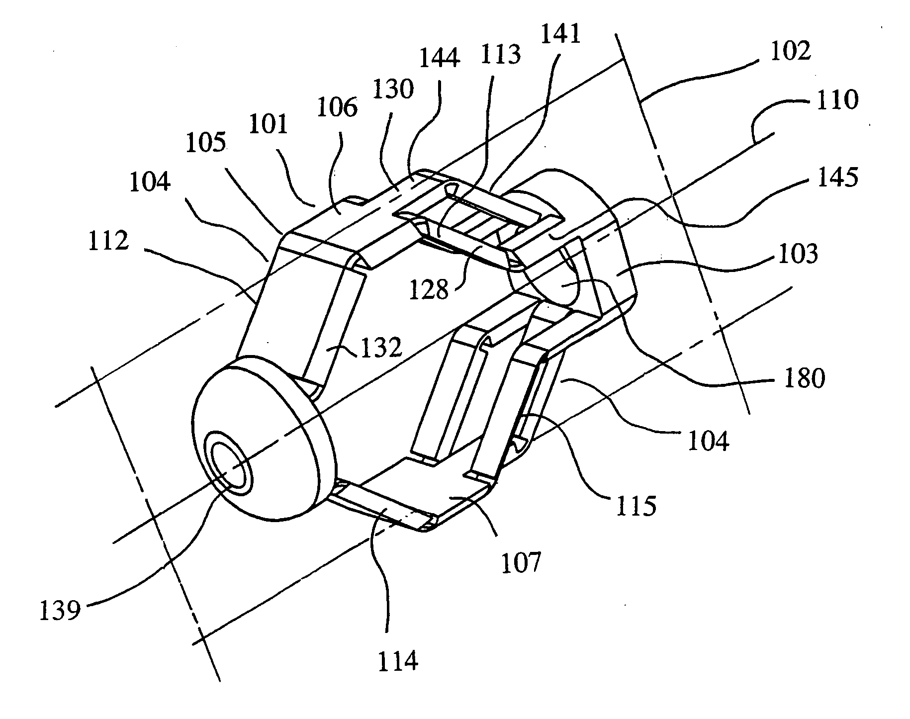
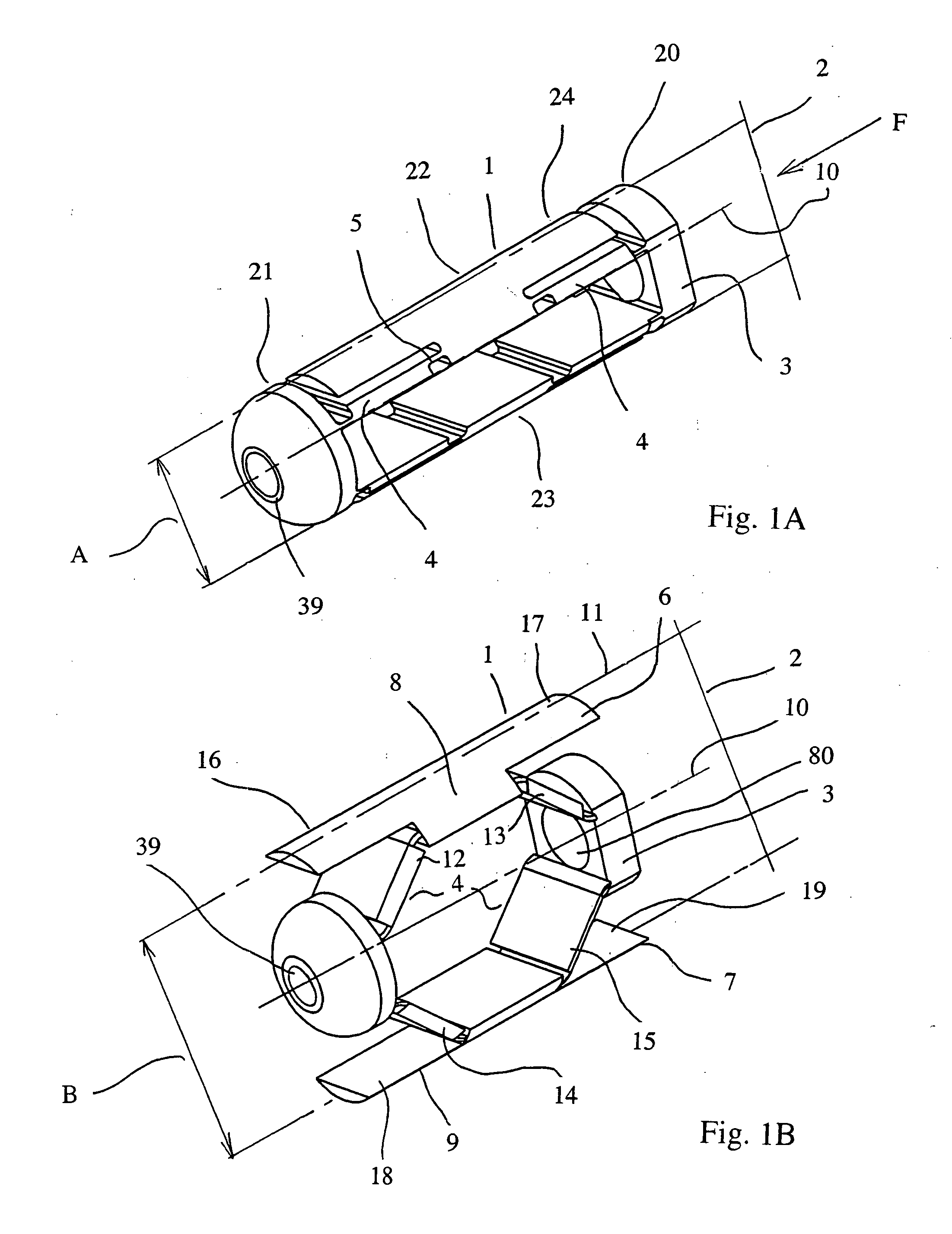
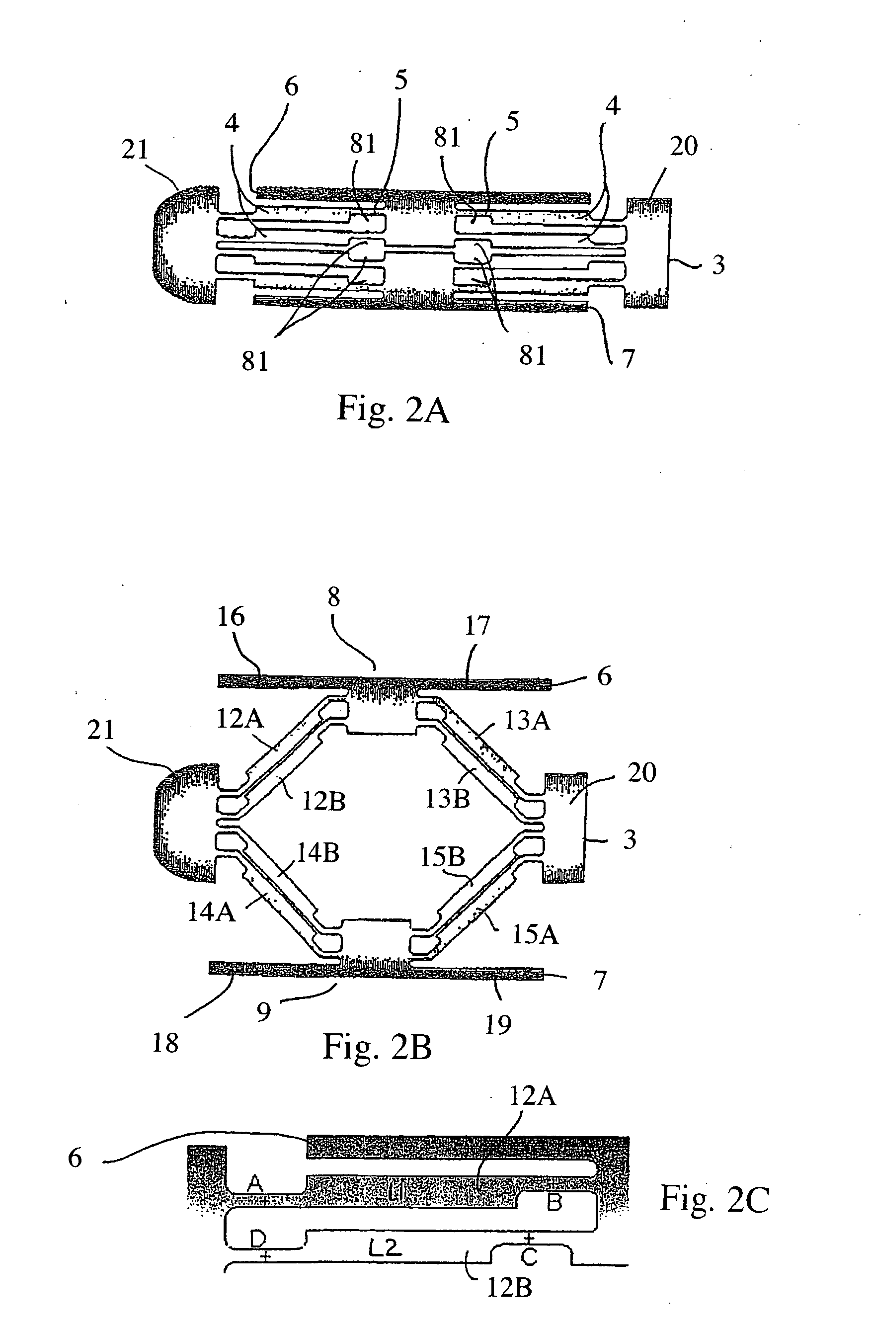
[0051] The expansible implant 1 represented in FIGS. 1A to 7 may include one or more of the following: [0052] a single determined expansion plane 2, which may be intrinsic to the implant, [0053] means 3 for positioning the expansible implant in the bone allowing the expansion plane to correspond with a bone restoration plane, [0054] means 4 for opening out the expansible implant in the single expansion plane 2, [0055] means 5 for controlling a determined expansion value, between a minimum thickness A of the implant before any expansion of the latter and a maximum thickness B of the implant after its maximum expansion, and [0056] a first 6 and a second 7 opposite plate which are able to form respectively a first 8 and a second 9 support surface in the bone intended to be moved apart one from the other along the single expansion plane 2 during expansion of the implant 1.

[0057] As shown in FIGS. 1A and 1B, implant 1 may include a cylindrical shape with a transverse circular exterior s...


PUM


Abstract

Methods and apparatuses for restoration of human or animal bone anatomy, which may include introduction, into a bone of an expansible implant capable of expansion in a single determined plane, positioning the expansible implant in the bone in order to correspond the single determined plane with a bone restoration plane and opening out the expansible implant in the bone restoration plane. A first support surface and a second support surface spread tissues within bone. The embodiments of the invention may also include injecting a filling material around the implant.

Description

CROSS REFERENCE TO RELATED APPLICATIONS [0001] This application is a continuation-in-part of U.S. patent application Ser. No. 10 / 951,766 filed on Sep. 29, 2004, which claims priority to French patent application No. 04 06211 filed on Jun. 9, 2004, the entire disclosures of which are hereby incorporated by reference.FIELD OF THE INVENTION [0002] The present invention relates to the field of surgery and medical implants and more particularly to devices and methods for restoring human or animal bone anatomy using medical bone implants. BACKGROUND OF THE INVENTION [0003] Various causes can be at the root of bone compression, in particular osteoporosis which causes (for example) natural vertebral compression under the weight of the individual, but also traumas, with the two causes occasionally being combined. Such bone compressions can affect the vertebrae but also concern other bones, such as the radius and the femur, for example. [0004] Several vertebroplasty techniques are known for e...

Claims


Application Information

Patent Timeline
Patent Type & Authority Applications(United States)
IPC IPC(8): A61F2/44A61F2/28A61F2/46A61B17/88A61B17/70A61F2/00A61F2/02A61F2/30
CPCA61B17/70A61F2002/30617A61F2/44A61F2/4611A61F2002/30224A61F2002/30471A61F2002/30556A61F2002/30579A61F2002/30601A61F2002/30772A61F2002/30774A61F2002/4627A61F2002/4629A61F2002/4635A61F2220/0091A61F2230/0069A61F2250/0009A61F2310/00023A61B17/8858A61F2/00A61F2/02A61F2/28A61F2002/30593A61F2/442A61F2/4425A61F2/4601
Inventor LEONARD, ALAINOGLAZA, JEAN-FRANCOIS
Owner STRYKER EUROPEAN OPERATIONS LIMITED
Why Eureka
Try Eureka