Steering force detection device for steering handle of vehicle

a detection device and steering handle technology, applied in the direction of steering initiation, instruments, vessel construction, etc., can solve the problems of reducing the steering ability of the vehicle, inaccurate detection of steering force devices, etc., to improve the detection accuracy of steering force, improve assembly accuracy, and facilitate alignment

Inactive Publication Date: 2006-01-05
YAMAHA MARINE KK
View PDF84 Cites 15 Cited by
  • Summary
  • Abstract
  • Description
  • Claims
  • Application Information

AI Technical Summary

Benefits of technology

[0013] As such, the received pressure detection section and the pressure receiving section can be easily aligned, preferably aligned coaxially. Alignment of the received pressure detection section and the pressure receiving section may be difficult when the detection section casing and the pressure receiving section casing (as separate members) are assembled to each other. Alignment of the received pressure detection section and the pressure receiving section may also be difficult when the detection section casing houses the received pressure detection section in its received pressure detection section mounting cavity. Alignment of the received pressure detection section and the pressure receiving section may also be difficult when the pressure receiving section casing houses the pressure receiving section in its pressure receiving section mounting cavity. However, the guide tube can be used to coaxially position the received pressure detection section and the pressure receiving section. This also improves the assembly accuracy of the detection section casing and the pressure receiving section casing. As a result, the steering force of the steering handle is transmitted directly from the pressure receiving section to the received pressure detection section, thus improving the detection accuracy of the steering force.
[0014] In some embodiments, the guide tube is configured to reduce or prevent movement of the received pressure detection section and / or the pressure receiving section disposed therein. The guide tube can have any number of ribs configured to engage the received pressure detection section or the pressure receiving section. The ribs can engage the received pressure detection section or the pressure receiving section mounted in the guide tube limit or prevent misalignment (e.g., leaning) of the received pressure detection section or the pressure receiving section. The ribs can therefore maintain the central position of the received pressure detection section or the pressure receiving section with respect to the guide tube.
[0015] In some embodiments, a sealing member is configured to form a seal between a fitting portion of the detection section casing and the pressure receiving section casing and a portion of an outside wall surface of the guide tube corresponding to the fitting portion. The fitting portion of the detection section casing and the pressure receiving section casing can be sealed. If the vehicle is a watercraft vehicle (e.g., a planing boat), water can be prevented from entering the guide tube. In some embodiments, the vehicle is a land vehicle (e.g., motorcycle) and containments (e.g., dust, rainwater, etc.) can be prevented from entering the guide tube.
[0016] In some embodiments, the fitting surfaces of the detection section casing and the pressure receiving section casing are somewhat flat and perpendicular to the pressure receiving direction of the pressure receiving section. This can improve the positional accuracy between the received pressure detection section and the pressure receiving section.

Problems solved by technology

When the vehicles are maneuvered at low speeds, the engine output may be very low thereby reducing the steerability of the vehicle.
However, the steering force detection device can be inaccurate, especially when the casing of the steering force detection device is not machined accurately.

Method used


Image

  • Steering force detection device for steering handle of vehicle
  • Steering force detection device for steering handle of vehicle
  • Steering force detection device for steering handle of vehicle

Examples


Embodiment Construction

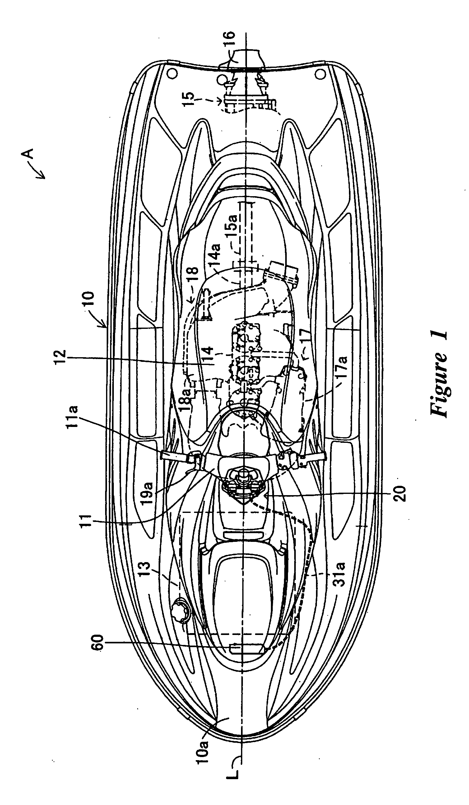
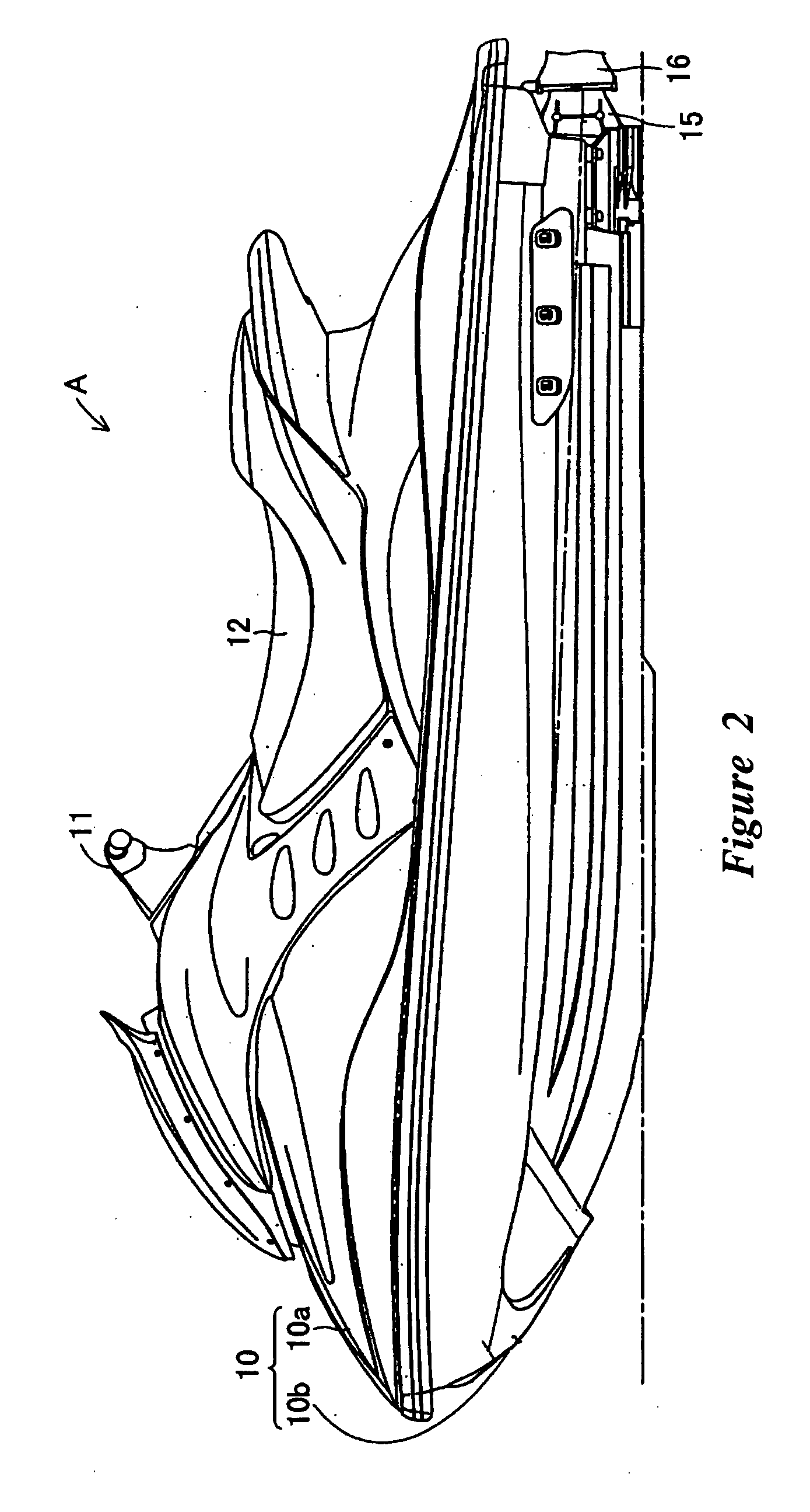
[0029]FIGS. 1 and 2 illustrate a small planing boat A (also commonly referred to as a “Personal watercraft”) including a preferred embodiment of the present steering-force detection device for a steering handle of a vehicle. The steering-force detection device is illustrated in the context of a personal watercraft because it has particular utility in this context. However, the steering-force detection device can also be used in other vehicles, including small jet boats, as well as other watercraft and land vehicles, including, but without limitation motorcycles.

[0030] With reference to FIG. 2, the small planing boat A has a boat body 10, including a deck 10a and a lower hull 10b. The boat body 10 can have steering handlebars 11 located slightly in front of its center on its upper part, and a seat 12 located centrally of the upper part. With reference to FIG. 1, a fuel tank 13 for storing fuel is disposed at the front bottom inside the boat body 10, and an engine 14 is disposed at t...


PUM


Abstract

A watercraft has steering force detection sections. Each steering force detection section includes a pressure receiving section. The pressure receiving sections are spaced from each other and are in the vicinity of a steering shaft. A pressing member is coupled to the steering shaft. The pressing member can press on at least one of the pressure receiving sections when the steering handlebars are rotated to a maximum steering angle. A received pressure detection section detects the pressure applied to the pressure receiving section. The pressure receiving section and the received pressure detection section are coaxially mounted in a pressure receiving section casing and a detection section casing. A guide tube can engage the pressure receiving section and the received pressure detection section. The guide tube is formed with ribs and grooves. The pressure receiving section has a pressure receiving member, a bolt, a plain washer, and a spring member.

Description

PRIORITY INFORMATION [0001] The present application is based on and claims priority under 35 U.S.C. § 119(a-d) to Japanese Patent Application No. 2004-169257, filed on Jun. 7, 2004, and Japanese Patent Application No. 2004-189350, filed on Jun. 28, 2004, the entire contents of which are expressly incorporated by reference herein. BACKGROUND OF THE INVENTIONS [0002] 1. Field of the Inventions [0003] The present inventions relate to a steering force detection device of a vehicle and, more particularly, to a steering force detection device that detects a steering force when a steering handle is rotated to a predetermined steering angle. [0004] 2. Description of the Related Art [0005] Vehicles typically have a steering device for controlling the direction that the vehicle travels. Personal watercraft or small planing boats often have a steering handle for controlling the direction the vehicle travels. These vehicles typically have a throttle lever disposed in the vicinity of a grip of t...

Claims


Application Information

Patent Timeline
Patent Type & Authority Applications(United States)
IPC IPC(8): G06F17/00
CPCB63H25/02
Inventor KANEKO, YOSHIYUKIKOYANAGI, TOMOYOSHIHARADA, YOSHINORIMIZUNO, YUTAKA
Owner YAMAHA MARINE KK
Why Eureka
Try Eureka