Thrust reverser comprising optimised deflector gratings

a technology of deflector grating and reverser, which is applied in the direction of climate sustainability, air transportation, jet propulsion plants, etc., can solve the problems of reducing the effectiveness of the two, reducing the aerodynamic braking performance of the airplane, etc., and achieves the effect of increasing the effectiveness of the reverse flow

Inactive Publication Date: 2006-01-12
HISPANO HUREL
View PDF22 Cites 26 Cited by
  • Summary
  • Abstract
  • Description
  • Claims
  • Application Information

AI Technical Summary

Benefits of technology

[0012] These objects are achieved by a cascade device having a reversed flow from the thrust flow of a turbojet engine, comprising a plurality of flow deflection cascades arranged side by side at the external periphery of an annular duct for the circulation of the thrust flow, each cascade consisting of a plurality...

Problems solved by technology

Bearing in mind the manufacturing installation tolerances, this clearance may prove to be large enough that it generates an air leak 32 in a vertical direction, or even one directed toward the rear of the nacelle, of a particularly great magnitude when the thrust is being reve...

Method used


Image

  • Thrust reverser comprising optimised deflector gratings
  • Thrust reverser comprising optimised deflector gratings
  • Thrust reverser comprising optimised deflector gratings

Examples


Embodiment Construction

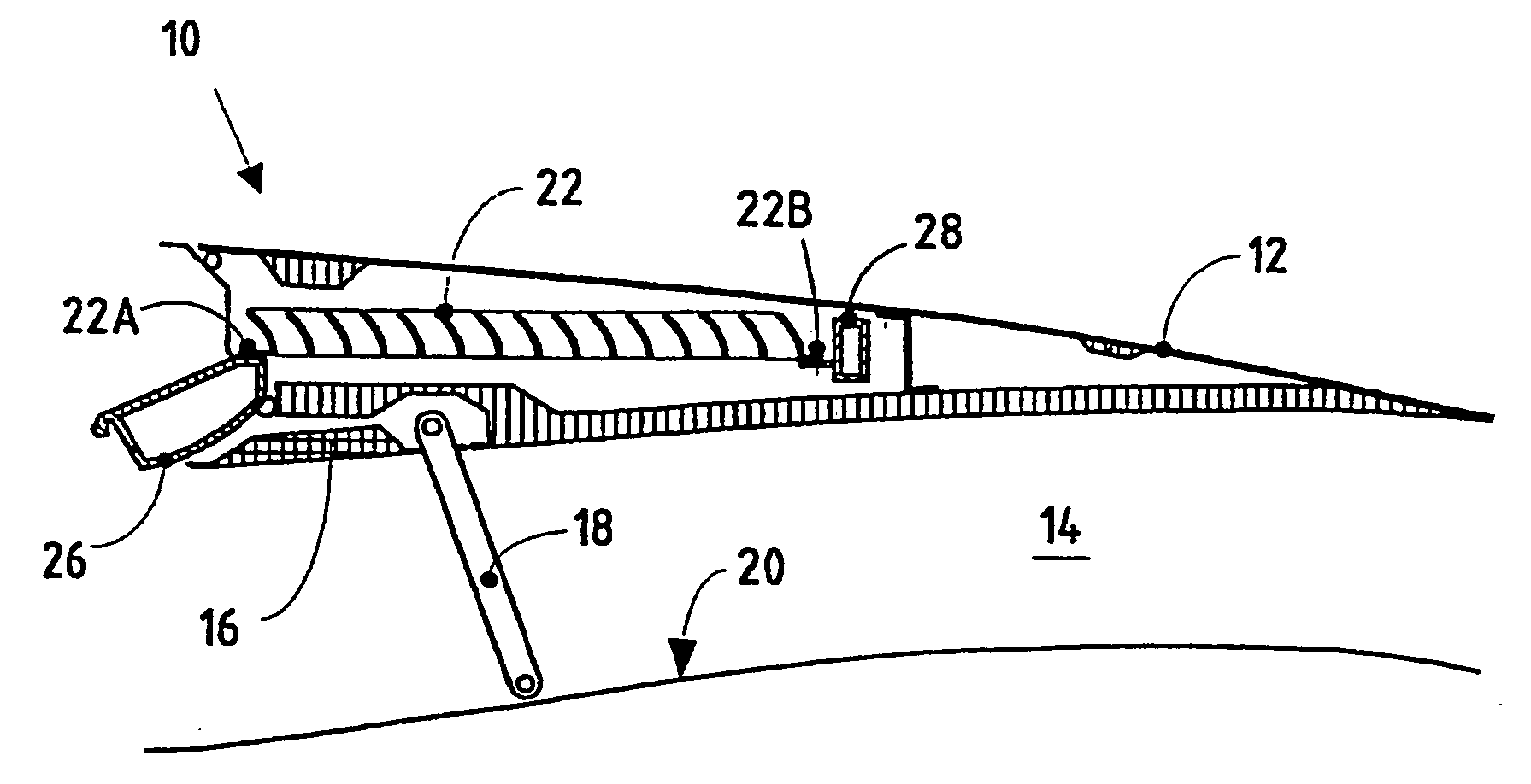
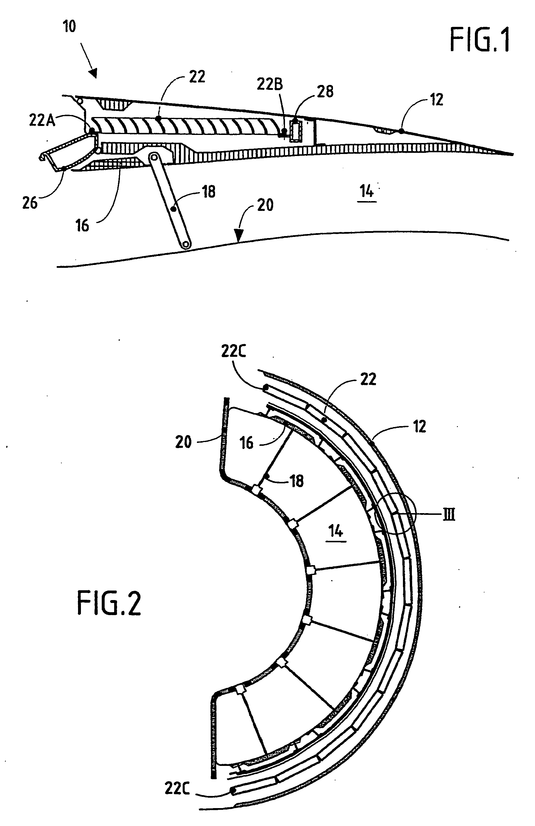
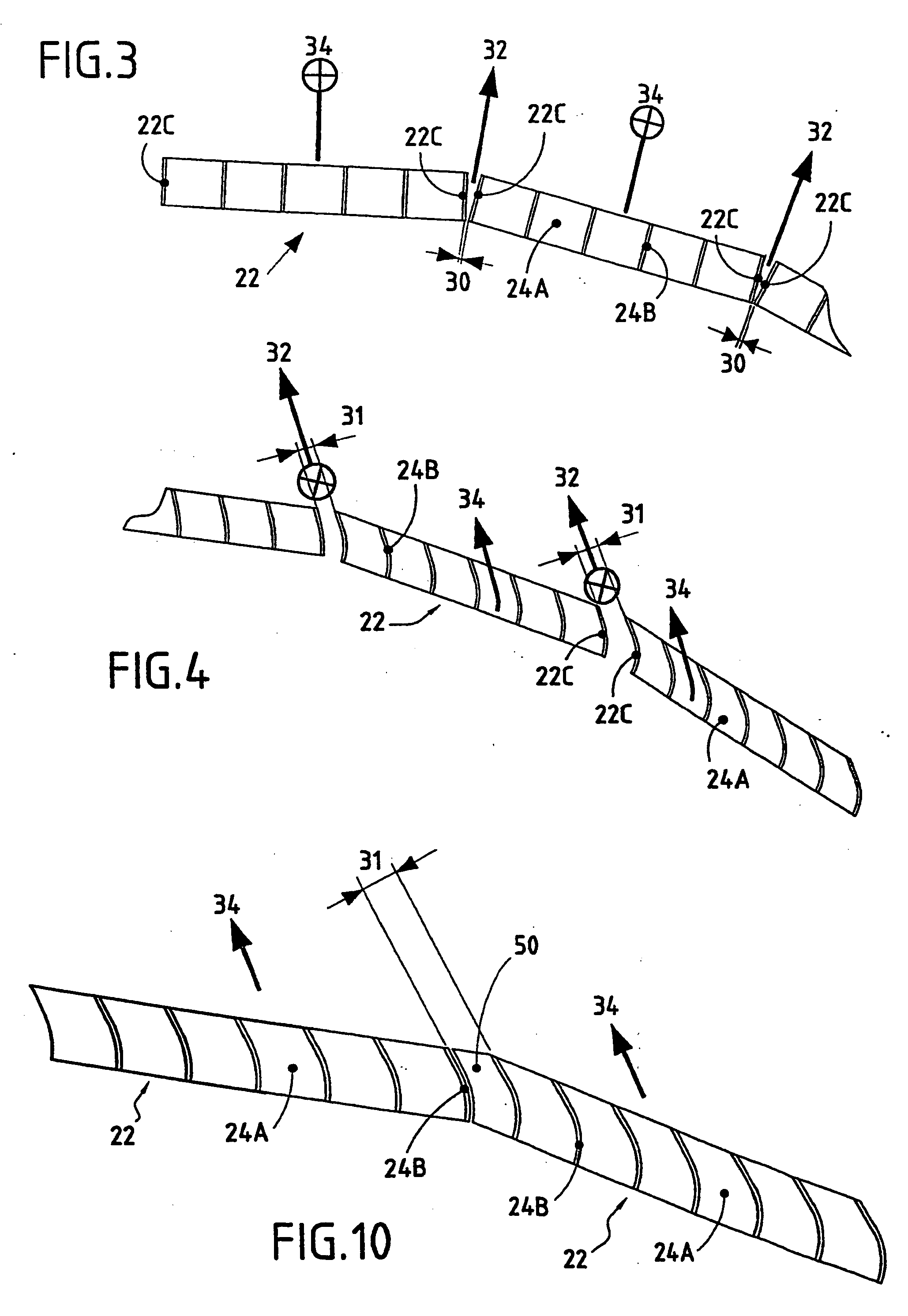
[0030] A first exemplary embodiment of the invention applied to a thrust reverser with its outlet forward (that is to say in a direction opposite to the airplane thrust direction) as illustrated in FIG. 5A to 5C. FIG. 5A is a schematic half view, in longitudinal section, of a thrust reverser with deflection cascades the cowling of which is depicted in the semi-open position. FIG. 5B is a partial view from above of the nacelle, cowling open, uncovering the cascades of the thrust reverser and FIG. 5C shows, in detail, the interface between two adjacent or middle cascades 22.

[0031] According to the invention, the cascade device comprises means for redirecting forward (in the direction of the reverse flow) the parasitic flow created by the air leak 32 and which was initially at best neutral or at worst generated thrust, so as to improve the effectiveness of the reverse flow. To do this, aerodynamic appendages in the form of transverse vane tips 36 mounted on a longitudinal external edg...


PUM


Abstract

The invention relates to a device comprising gratings, which are used to form a reverse flow from a jet engine thrust flow. The inventive device comprises a plurality of flow diverter gratings which are disposed side-by-side at the outer edge of an annular thrust flow circulation channel. Each of the gratings comprises a plurality of intersecting inner transverse blades and inner longitudinal blades, two adjacent gratings being separated by a side clearance which generates a leakage flow. The device also comprises means of re-directing the aforementioned leakage flow in a direction such as to increase the effectiveness of the reverse flow, said re-direction means comprising aerodynamic appendages which are mounted to at least one outer longitudinal edge of each grating.

Description

FIELD OF THE INVENTION [0001] The present invention relates to thrust-reversal devices for bypass turbojet engines and relates more specifically to an improvement to the flow deflection cascades also known as gratings used inside such devices. PRIOR ART [0002] Conventionally, a bypass turbojet engine is equipped with a passage behind the fan and whose purpose is to channel the so-called cold secondary flow. This passage is made up of an internal wall surrounding the structure of the actual engine behind the fan, and of an external wall the upstream part of which is a continuation of the engine casing which surrounds this fan. This external wall can channel both the secondary flow and the primary flow in its downstream part, this being behind the ejection of the so-called hot primary flow in the case of mixed-flow nacelles or confluent-flow nacelles for example. By contrast, in the case of so-called separate-flow nacelles, the external wall channels only the secondary flow. [0003] On...

Claims


Application Information

Patent Timeline
IPC IPC(8): F02K1/54F02K1/62F02K1/72F02K3/04
CPCF02K1/625F02K1/72F05D2240/12Y02T50/671F02K3/04Y02T50/60
Inventor BLIN, LAURENT ALBERTCAZUC, XAVIERVAUCHEL, GUY BERNARD
Owner HISPANO HUREL
Why Eureka
Try Eureka