Clamp structure of an external electrode lamp

a technology of external electrodes and clamps, which is applied in the direction of gas-filled discharge tubes, instruments, optics, etc., can solve the problems of high failure rate, serious scorch or electric leakage, and complicated process of welding or copper belting, so as to achieve strong resistance and effectively increase the safety and reliability of the produ

Active Publication Date: 2006-01-12
HANNSTAR DISPLAY CORPORATION
View PDF2 Cites 58 Cited by
  • Summary
  • Abstract
  • Description
  • Claims
  • Application Information

AI Technical Summary

Benefits of technology

[0013] It is an advantage of the present invention that the clamp structure provides distinguishing features including well adapted cladding ability and strong resistance to shocks and impacts, thereby effectively increasing the safety and reliability of the product.
[0014] These and other objectives of the present invention will no doubt become obvious to those of ordinary skill in the art after reading the following detailed description of the preferred embodiment that is illustrated in the various figures and drawings.

Problems solved by technology

Nevertheless, welding or copper belting are both complicated processes that also bear high failure rates.
For example, poor soldering often causes a so-called fake welding effect, in which the heat generated during lighting will produce temperature high enough to melt the solder of the section where the conducting end is connected to the conducting wire and eventually results in a broken circuit.
If the excess solder of the section between the conducting end and the conducting wire is poor, an electric discharge often results and causes serious scorch or electric leakage.
On the other hand, if copper belting is used, electric discharge at the four corners of the copper belt has to be considered carefully, and in general, an additional insulated heat-shrink tube is added to cover the external area of the copper belt which unavoidably results in extra cost.
Despite the fact that this patent design could essentially solve the problems discussed previously, the luminosity and life expectancy of the lamp have been strongly challenged as the development of backlight lamp advances and as the size of LCD panel increases.
During regular testing, as the electrode of the EEFL is constantly driven by high voltages and exposed to the outside environment, numerous electric shocks would frequently take place.
In addition, the layout of the electrode power supply resulting from stabilizing the external electrode lamp in position also places various limitations on the shock resistance design.
Consequently, many of the EEFL products sold in the market today still suffer from problems such as poor electrode cladding or poor shock resistance.

Method used


Image

  • Clamp structure of an external electrode lamp
  • Clamp structure of an external electrode lamp
  • Clamp structure of an external electrode lamp

Examples


Embodiment Construction

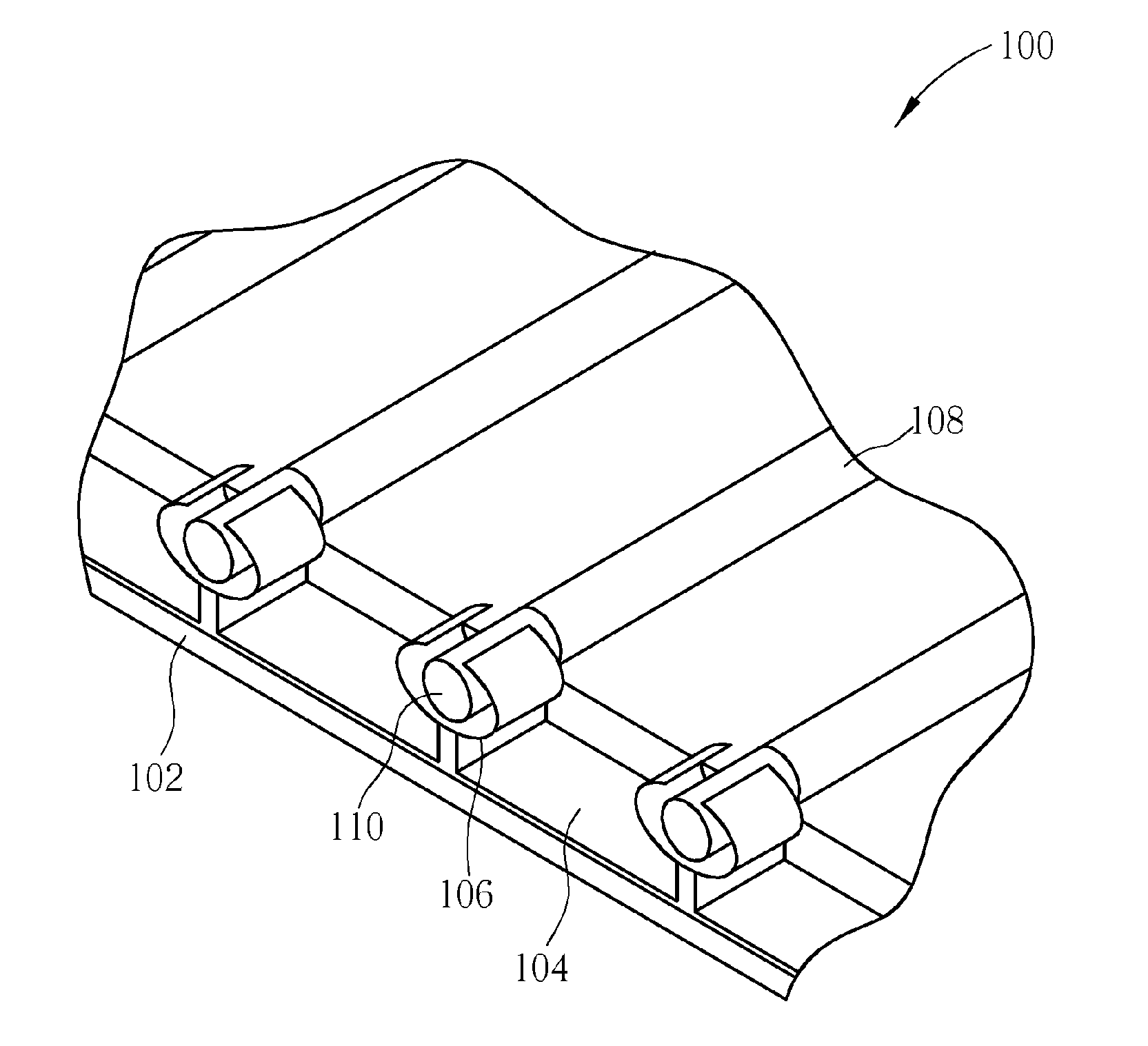
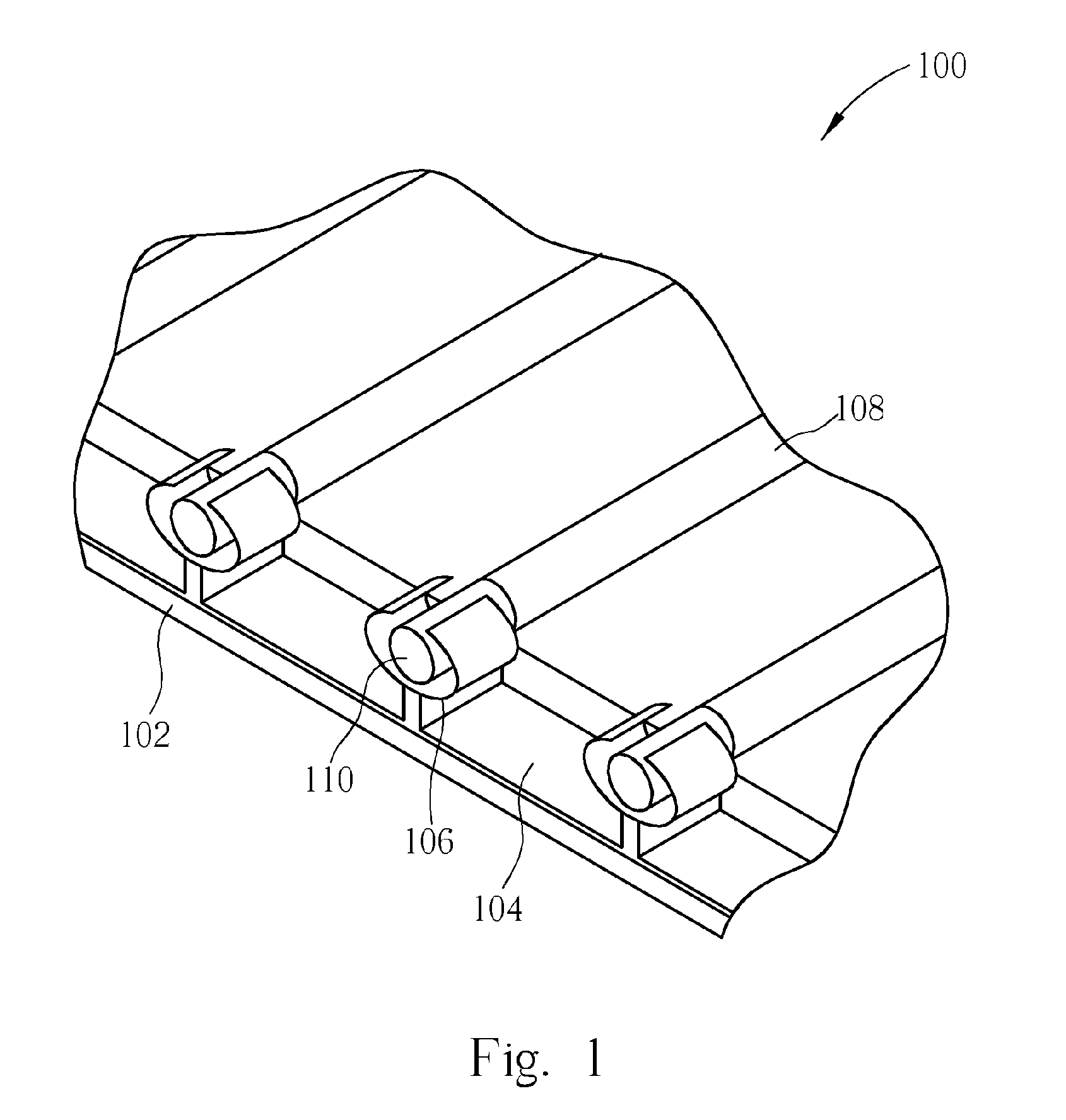
[0018] Please refer to FIG. 1. FIG. 1 is a diagram of a clamp structure of an external electrode lamp according to the present invention. As shown in FIG. 1, a clamp structure 100 includes a base 102, a metal strip 104, and a row of metal clipping channel 106. The entire row of metal clipping channel 106 is fixed in place by the metal strip 104 and when an external electrode lamp 108 is installed into the clamp structure 100, a parallel connection will be established. The connection between the external electrode lamp 108 and the clamping structure 100 is essentially achieved by installing and clamping the electrode 110 of the external electrode lamp 108 into the metal clipping channel 106 via its metal elasticity. The metal strip 104 is then electrically connected to an inverter (not shown) for providing power from the inverter to each metal clipping channel 106. By contacting the external electrode lamp 108 with the metal clipping channel 106 directly, the power can be delivered s...


PUM


Abstract

A clamp structure of an external electrode lamp includes a first fixing device, a second fixing device, and a metal strip. The first fixing device has a first indentation and the second fixing device has a second indentation for clamping an electrode of the external electrode lamp. In addition, the metal strip is located between the first and second fixing devices to contact the electrode of the external electrode lamp for providing power. The electrode can be further equipped with a cushion for fixing the electrode onto the first and second fixing devices.

Description

BACKGROUND OF INVENTION [0001] 1. Field of the Invention [0002] The invention relates to a clamp structure, and more particularly, to a clamp structure of an external electrode lamp. [0003] 2. Description of the Prior Art [0004] Most lamps used in TFT-LCD backlight modules today are cold cathode fluorescent lamps (CCFL) and the electrodes of these lamps are essentially sealed inside the lamp. The electrode however, also contains a conducting end that extends from the internal electrode to an external conducting wire, and eventually connects to a power supply to light the lamp. [0005] The conducting end of the CCFL essentially needs to be connected via welding or a copper belt to the conducting wire. Nevertheless, welding or copper belting are both complicated processes that also bear high failure rates. For example, poor soldering often causes a so-called fake welding effect, in which the heat generated during lighting will produce temperature high enough to melt the solder of the s...

Claims


Application Information

Patent Timeline
Patent Type & Authority Applications(United States)
IPC IPC(8): H01J11/00
CPCG02F1/133604H01J65/046H01J61/305H01J61/0672
Inventor HUANG, CHI-JENLAI, HSIN CHIEH
Owner HANNSTAR DISPLAY CORPORATION
Why Eureka
Try Eureka