Low profile magnetic element

Active Publication Date: 2006-01-12
DET INT HLDG LTD
View PDF6 Cites 32 Cited by
  • Summary
  • Abstract
  • Description
  • Claims
  • Application Information

AI Technical Summary

Benefits of technology

[0007] The magnetic component structure of this invention provides an improved magnetic core and winding arrangement. For transformer construction, it is highly suitable for higher current applications. The invention will all

Problems solved by technology

The continuous trend for lower voltages and higher current has set new challenges for power magnetic components such as transformers.
In such applications the copper thickness is limited.
This limitation will exclude applications wherein large currents are processed, which today is the growin

Method used


Image

  • Low profile magnetic element
  • Low profile magnetic element
  • Low profile magnetic element

Examples


Embodiment Construction

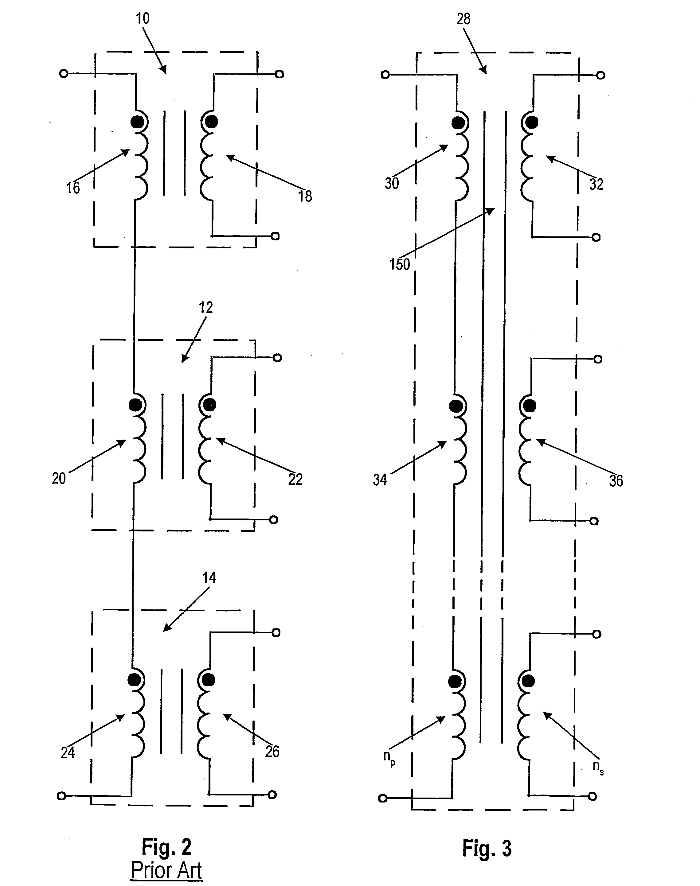
[0028] Turning to FIG. 3, a transformer structure 28 according to the invention is shown schematically. To split the output current, independent secondary windings are used, such as 32, 36 . . . ns. Typically, for high current, these secondary windings have only one turn. Primary windings of the transformer 28 are also split in the same number of sections as the secondary. These sections 30, 34 . . . np are close coupled with their equivalent secondary 32, 36 . . . ns. In this way a close coupling between primary and secondary is formed. The magnetic flux in a magnetic core 150 used by the structure 28 links all of the windings. For comparison, FIG. 2 is a schematic representing the prior art concept wherein independent transformer structures are used for splitting the output current. As mentioned before, in this prior art approach, the magnetizing current is lower and it leads to a larger magnetizing current and lower efficiency.

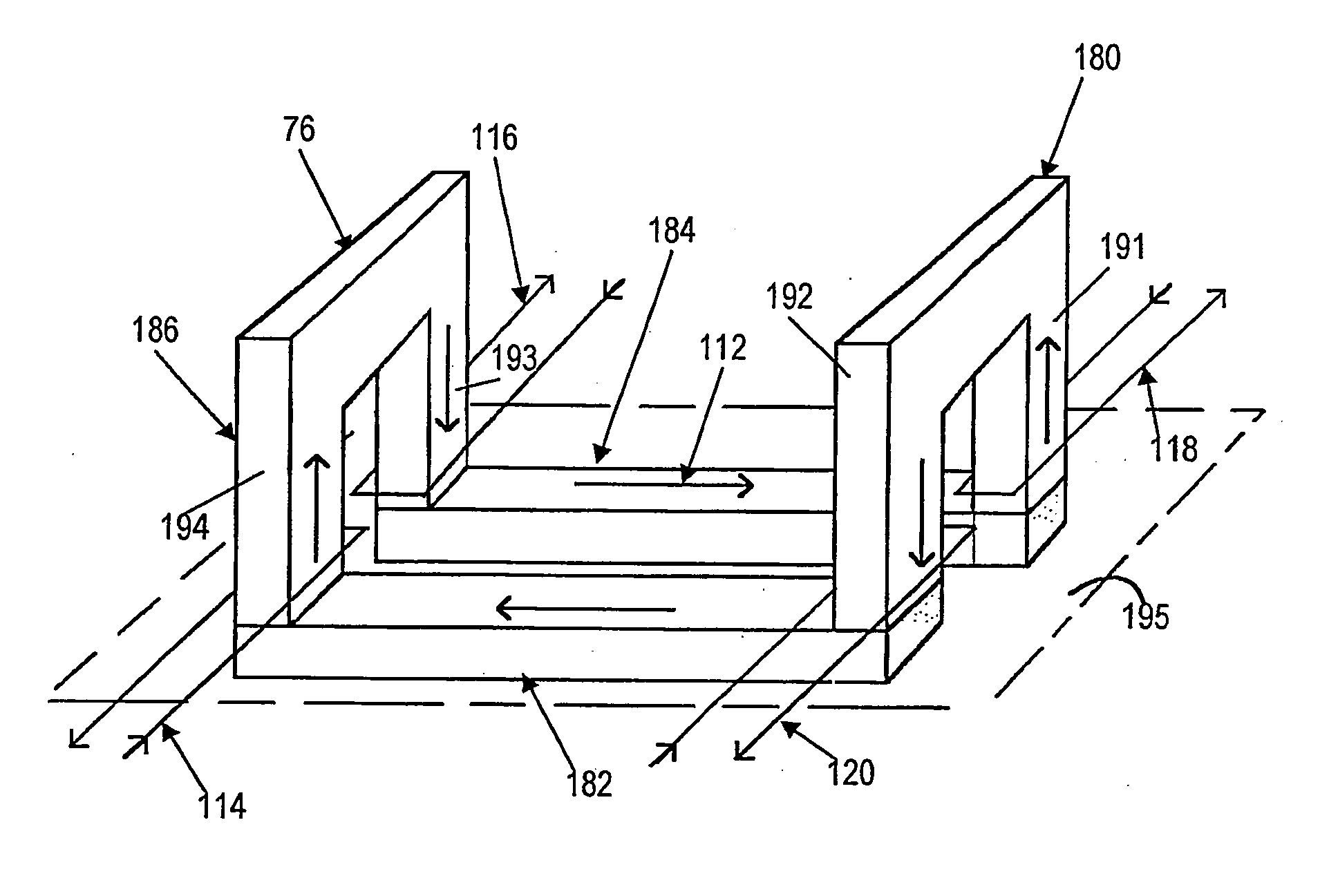
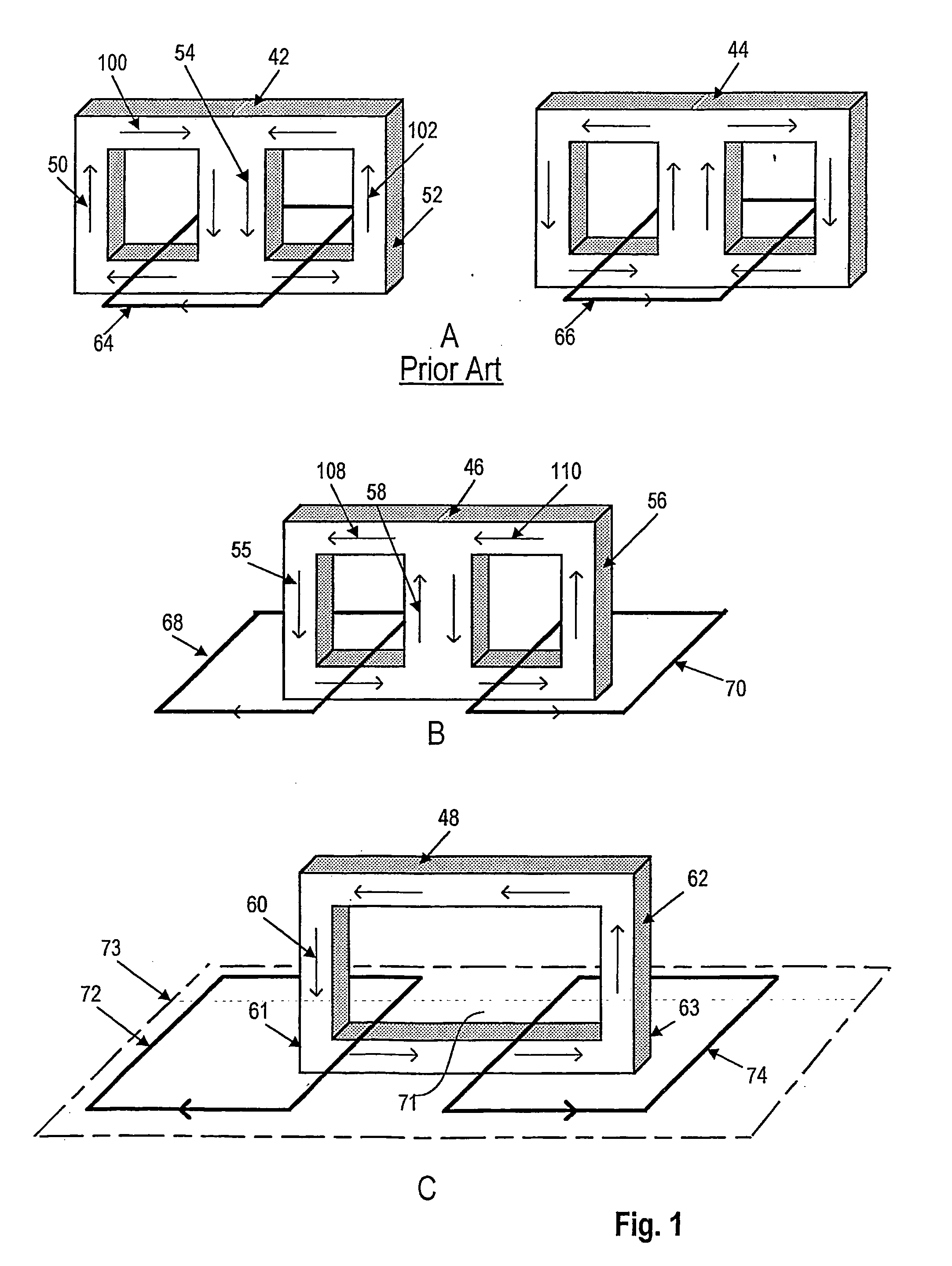
[0029]FIG. 1 demonstrates the transition from the pr...


PUM

PropertyMeasurementUnit
Electrical conductoraaaaaaaaaa
Magnetismaaaaaaaaaa

Abstract

A low profile magnetic element used in cooperation with a multilayer printed circuit board has two or more core arms penetrating the board from one outer surface to the other and a series of magnetic core elements, at least one on each side of the board, bridging pairs of the core arms to form a closed, unbranched flux path. Series-connected windings form a transformer primary and are wound on the core arms that penetrate the board. Parallel-connected windings form a transformer secondary and are also wound on the core arms. The series-connected windings and the parallel-connected windings may be buried windings printed on internal surfaces of the multilayer board. The connected in series primary windings all have the same number of turns and the parallel-connected secondary windings all have the same number of turns. The parallel secondary windings are connected in current additive fashion to afford a high current transformer output. Output treating circuitry can treat each output separately in parallel and identically, being connected between the winding outputs and their point of connection. The transformer core can be assembled entirely of C and I magnetic elements. In one embodiment, a pair of magnetic plates overlying the outer surfaces of the multilayer circuit board are in flux-conducting relation with all of the core arms penetrating the board.

Description

CROSS REFERENCE TO RELATED APPLICATIONS [0001] Priority is claimed from U.S. provisional patent application Ser. No. 60 / 372,279 entitled “Low Profile Magnetic Element” filed Apr. 12, 2002 in the name Ionel D. Jitaru and Marco Davila. That application is incorporated herein by reference.FIELD OF THE INVENTION [0002] This invention relates to mechanical construction and its electrical results for planar inductors and planar transformers used in power conversion. BACKGROUND OF THE INVENTION [0003] The industry demand for increasing power density and lowering the height of power converters imposed the use of planar inductors and planar transformers. The continuous trend for lower voltages and higher current has set new challenges for power magnetic components such as transformers. In order to simplify and control the manufacturing process for power magnetic components, the windings are embedded or buried within multilayer PCB structures. In such applications the copper thickness is limi...

Claims


Application Information

Patent Timeline
IPC IPC(8): H01F27/24H01F27/28
CPCH01F27/24Y10T29/4902H01F27/2804
Inventor JITARU, IONEL D.DAVILA, MARCO A.
Owner DET INT HLDG LTD
Why Eureka
Try Eureka