Shaft current control brush ring assembly

a brush ring and shaft current technology, applied in electrostatic charges, electrostatic charges, and arrangements responsive to excess voltage, etc., can solve the problems of high common mode voltage (cmv), shaft induced current, and buildup of charge on the shaft surface, so as to reduce the shaft current of electrical motors, reduce the effect of shaft current on electrical motors and effective conductive brush assemblies

Active Publication Date: 2006-01-12
ILLINOIS TOOL WORKS INC
View PDF44 Cites 67 Cited by
  • Summary
  • Abstract
  • Description
  • Claims
  • Application Information

AI Technical Summary

Benefits of technology

[0012] An advantage of the present invention is providing an effective conductive brush assembly to reduce shaft current on electrical motors.
[0013] Another advantage of the present invention is providing a grounding device for electrical motor shafts that functions effectively for a prolonged period of time without service, maintenance or repair.
[0014] Still another advantage of the present invention is providing a conductive brush system having improved conductivity therethrough for improved grounding performance of the device through precise, optimal positioning of the components thereof.
[0015] A still further advantage of the present invention is providing a grounding device for electrical motors that is readily adapted to motors of different sizes.
[0016] Yet another advantage of the present invention is providing a shaft current control brush ring assembly that can be installed quickly and easily in new motors during manufacture or can be retrofit on existing motors without significant modification to the motor.
[0017] Other features and advantages of the invention will become apparent to those skilled in the art upon review of the following detailed description, claims and drawings in which like numerals are used to designate like features.

Problems solved by technology

A drawback to the use of AC motors with variable speed drives is that higher common mode voltage (CMV) is generated by the variable speed drive that increases shaft induced currents.
While the motor is running, the bearings become more resistive to current flow, causing a buildup of charge on the shaft surfaces.
This discharge causes electric discharge machining (EDM), which can damage the surfaces of the bearing races and the balls in the bearing.
Both the fusion crater and the particulate material in the bearing act to disturb the free flow rotation of the bearing, which can lead to physical damage and premature bearing failure.
Copper brushes, however, wear out quite rapidly and require frequent, periodic service and replacement.
Additionally, oxide build-up on the shaft and other barriers between the brushes and the shaft reduce the current flow and cause a burst of electrical energy across the brush and shaft.
Spring-loaded brushes also tend to vibrate due to alternating frictional stick / slip relationships between the brush and the shaft surface.
Vibration of the brushes, from whatever cause, can result in undesirable sparking.

Method used


Image

  • Shaft current control brush ring assembly
  • Shaft current control brush ring assembly
  • Shaft current control brush ring assembly

Examples


Embodiment Construction

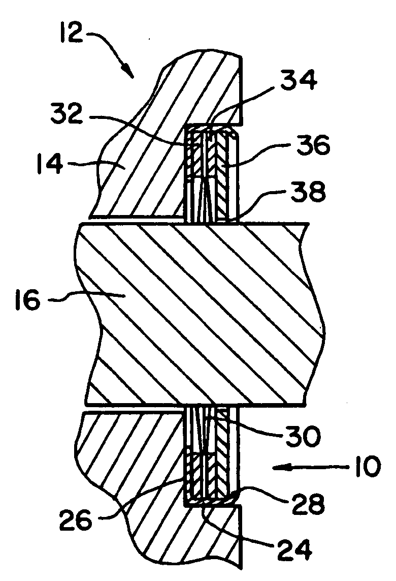
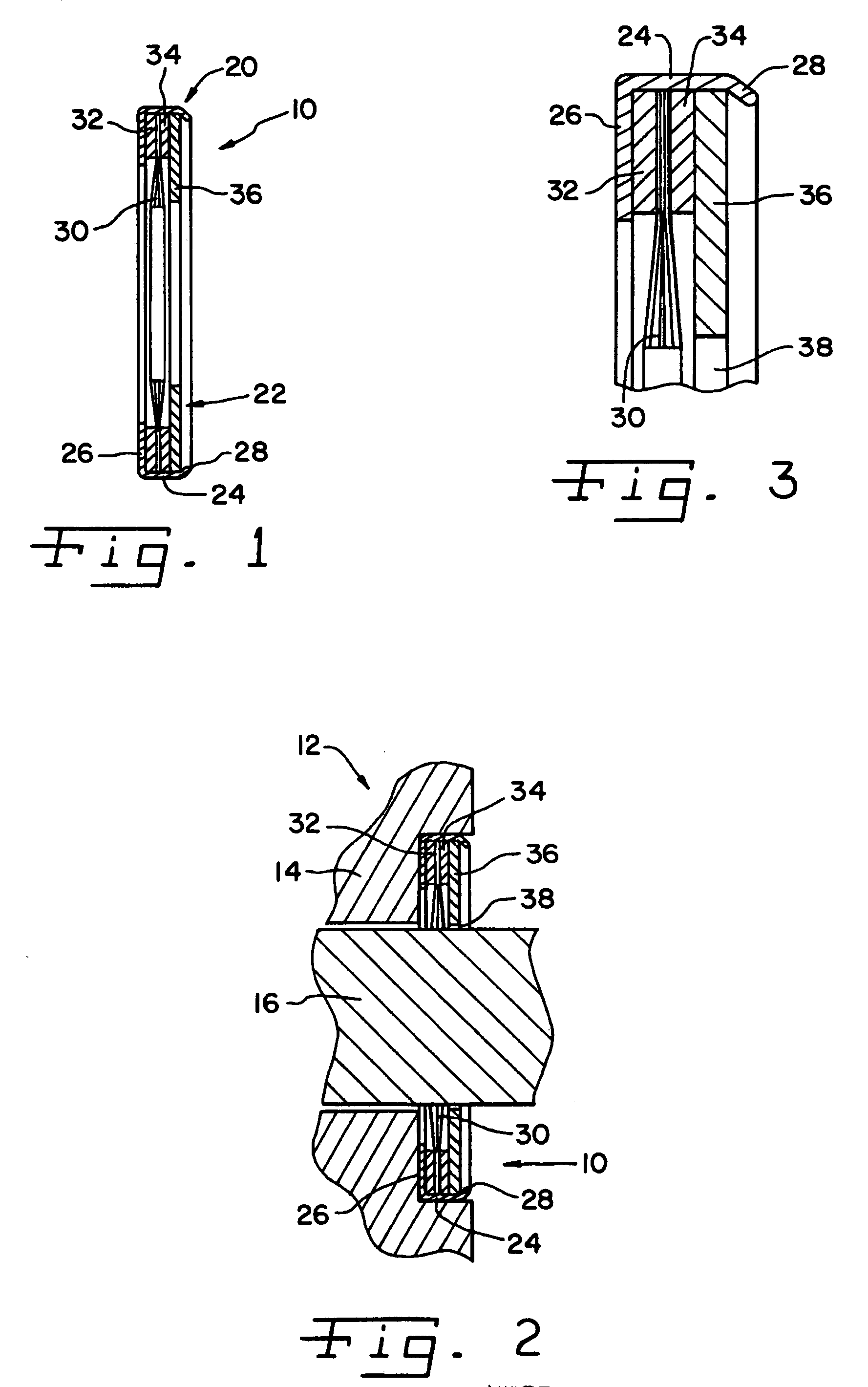
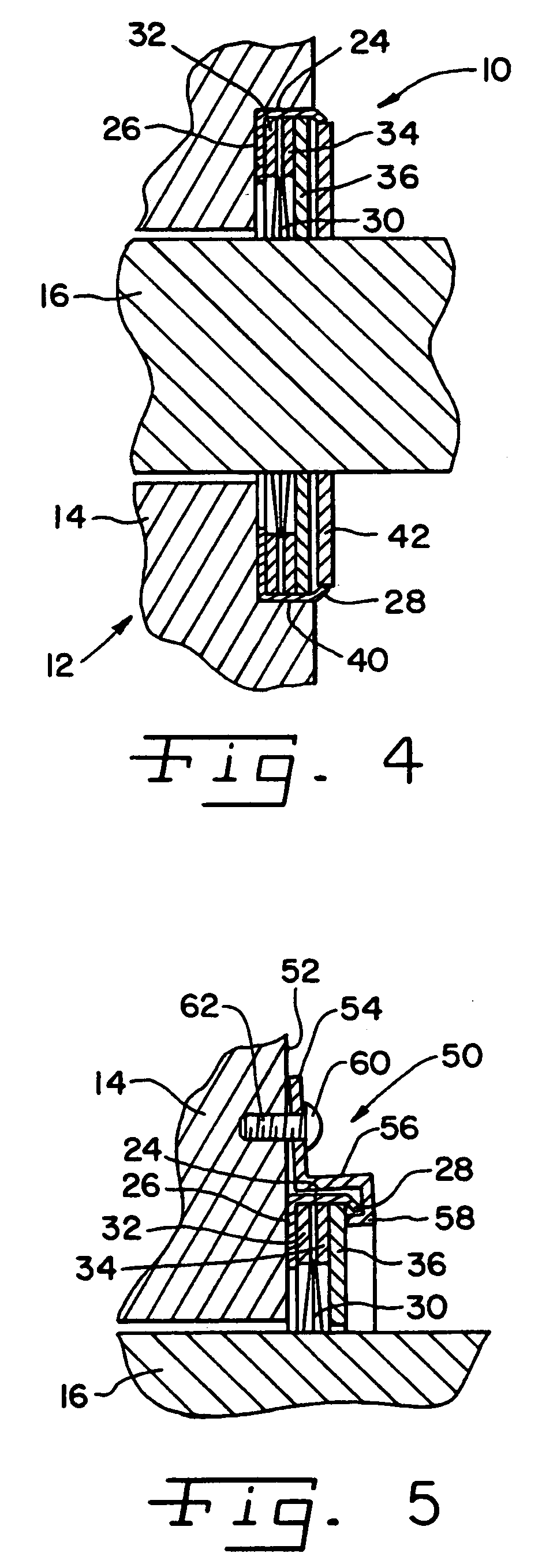
[0024] Referring now more specifically to the drawings and to FIG. 1 in particular, numeral 10 designates a shaft current control brush ring assembly in accordance with the present invention. Brush ring assembly 10 is installed on a motor 12 (FIG. 2) and specifically in a faceplate 14 of motor 12 for dissipating electrical charges that may build up on a shaft 16 of motor 12. It should be understood that brush ring assembly 10 can be provided in a variety of different sizes for use in motors of different types and on shafts 16 of different diameters.

[0025] Brush ring assembly 10 is of generally annular shape, surrounding shaft 16. Brush ring assembly 10 is secured to faceplate 14 and is operatively arranged between shaft 16 and faceplate 14. Brush ring assembly 10 is continuously operative to dissipate electrical charges that build on motor shaft 16 during operation of motor 12 by transferring the charges from shaft 16 to faceplate 14 and the grounding circuit of motor 12.

[0026] Br...


PUM


Abstract

A shaft current control brush ring assembly includes a cup and a brush ring assembly secured within the cup. The cup is secured to a motor faceplate, within a recess formed in the faceplate by interference fit, or by means of a clamp attached to the faceplate. A slinger can be associated with the brush ring assembly.

Description

CROSS-REFERENCE TO RELATED APPLICATIONS [0001] The present application claims the benefit of U.S. Provisional Application Ser. No. 60 / 673,308 filed on Apr. 20, 2005, and is a continuation-in-part of co-pending U.S. patent application Ser. No. 10 / 877,112 filed on Jun. 25, 2004, which claims the benefits of U.S. Provisional Application Ser. No. 60 / 508,949, filed Oct. 6, 2003, and U.S. Provisional Application Ser. No. 60 / 508,950, also filed Oct. 6, 2003, and is a continuation-in-part of co-pending U.S. application Ser. No. 10 / 714,295, filed on Nov. 14, 2003, which claims the benefit of U.S. Provisional Application Ser. No. 60 / 455,301, filed on Mar. 17, 2003.FIELD OF THE INVENTION [0002] The present invention relates to grounding devices for controlling shaft current that is generated in AC variable speed motors or DC motors, generators, and other rotating shafts and, more specifically, to non-contacting grounding devices. BACKGROUND OF THE INVENTION [0003] Shaft induced electrical curr...

Claims


Application Information

Patent Timeline
Patent Type & Authority Applications(United States)
IPC IPC(8): H02H7/08
CPCH02K11/0089H02K11/40
Inventor OH, HIEYOUNG W.WILLWERTH, ADAM H.
Owner ILLINOIS TOOL WORKS INC
Why Eureka
Try Eureka