Method and apparatus for performing adaptive control of beam forming

a beam forming and beam technology, applied in multiplex communication, polarisation/directional diversity, wireless commuication services, etc., can solve the problems of local degradation, high interference spot, and non-uniform power distribution radiated from the antenna, so as to prevent the reduction of user throughput per sector

Inactive Publication Date: 2006-01-12
FUJITSU LTD
View PDF8 Cites 26 Cited by
  • Summary
  • Abstract
  • Description
  • Claims
  • Application Information

AI Technical Summary

Benefits of technology

[0016] Therefore, it is an object of the invention to provide an adaptive control technique for beam formation of a directional sector antenna, which can prevent reduction of the user throughput per sector.

Problems solved by technology

For this reason, the power distribution radiated from the antenna becomes spatially non-uniform, being biased toward a direction with a high user density or a high antenna gain.
The undesirable power concentration causes a high interference spot and local degradation at that spot, and the throughput is reduced.
This situation is likely to occur when the directivity gain of the directional sector antenna is steep, that is, when the antenna half beamwidth is narrow.
From the above discussion, it appears to be difficult to choose the maximum spatial power path as the optimum channel.
This means that it becomes more difficult to prevent reduction of the throughput due to local degradation of spots.
For the downlink beam formation, a null steering technique is proposed; however, no consideration is made on optimization of transmit direction for the main beam.

Method used


Image

  • Method and apparatus for performing adaptive control of beam forming
  • Method and apparatus for performing adaptive control of beam forming
  • Method and apparatus for performing adaptive control of beam forming

Examples


first embodiment

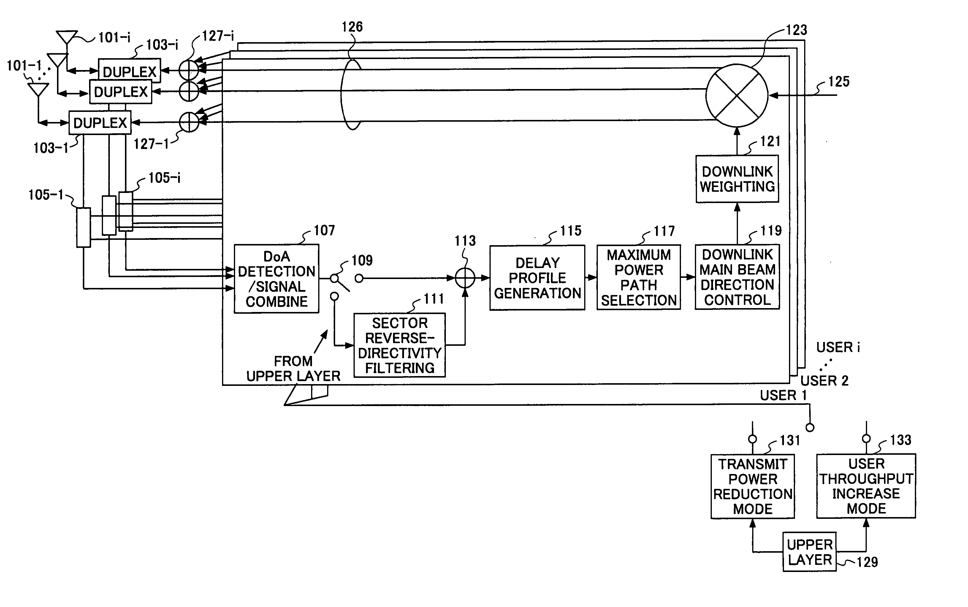
[0043]FIG. 3 is a schematic diagram of a beam-forming adaptive control apparatus according to the invention. The beam-forming adaptive control apparatus includes antennas 101-1 through 101-i, duplexers 103-1 through 103-i for isolating transmitters from a receivers, user separators 105-1 through 105-i, a DoA (direction of arrival) detection / signal combining unit 107, a mode switch 109, a sector reverse-directivity filter 111, an adder 113, a delay profile generator 115, a maximum power path selector 117, a downlink main beam direction control unit 119, a downlink weighting unit 121, a multiplier 123, and user multiplexing units 127-1 through 127-i.

[0044] A signal processing section that comprises the DoA detection / signal combining unit 107, the mode switch 109, the sector reverse-directivity filtering unit 111, the adder 113, the delay profile generator 115, the maximum power path selector 117, the downlink main beam direction control unit 119, the downlink weighting unit 121, the ...

second embodiment

[0061]FIG. 5A illustrates an example of the signal power distribution of a 60-degree sector antenna in the throughput increase mode. FIG. 5B illustrates an improved signal power distribution of the same sector antenna operating under optimization control, which will be described in the The dashed arrows, the solid arrows, the lengths of the arrows, and the thickness of the lines indicate the same parameters as those shown in FIG. 4.

[0062] The distribution depicted in FIG. 5A shows the direction of the main beam to be transmitted, which is determined based on the DoA information and the signal power received at the antenna.

[0063] The major difference from the distribution shown in FIG. 4 is that the desired transmit direction of the user data has a substantially uniform distribution. The antenna transmit power at the end of the antenna becomes greater in the direction with less antenna gain, and consequently, the transmit power per sector increases.

[0064] However, the spatial sign...


PUM


Abstract

In a beam forming adaptive control method, a signal of each mobile station is separated from a set of signals received at a sector antenna from multiple mobile stations. The signals are transmitted in a code division multiple access scheme. The direction of arrival and the received power level of each path of the separated signals is calculated for each of the mobile stations. Then, spatial signal power level immediately before the signal is received at the antennas is estimated from the received power levels, based on the respective direction of arrival and sector antenna gain. Finally, the direction of the beam to be transmitted is determined based on the estimated spatial signal power level.

Description

BACKGROUND OF THE INVENTION [0001] 1. Field of the Invention [0002] The present invention generally relates to a Code Division Multiple Access (CDMA) cellular mobile communications technique, and more particularly, to digital beam forming applied to an adaptive array of directional sector antennas. [0003] 2. Description of the Related Art [0004] In general, cellular mobile communications systems operate in a multi-path environment. [0005] An uplink multi-path signal (from a mobile station to a base station) is received at the base station from different direction of arrival (DoA), with different time delay, and under different fading effect, due to scattering, diffraction, reflection, or other factors. With a Time Division Duplex (TDD) scheme, a reversible channel may be established on downlink from the base station to the mobile station because the same frequency is used for uplink and downlink in TDD wireless communications. With a Frequency Division Duplex (FDD) scheme, adjacent ...

Claims


Application Information

Patent Timeline
Patent Type & Authority Applications(United States)
IPC IPC(8): H04Q7/00H04B1/69H04B7/06H04B7/08H04B7/10H04J13/00H04W16/28
CPCH04B7/086
Inventor YOKOYAMA, HITOSHI
Owner FUJITSU LTD
Why Eureka
Try Eureka