Video coding apparatus and video decoding apparatus

a video coding and video decoding technology, applied in the field of video coding apparatus and video decoding apparatus, can solve the problems of weakening the error resilience of transmission data, and achieve the effect of high noise resilience in transmission and error resilien

Inactive Publication Date: 2006-01-12
NAGAI TAKESHI +2
View PDF7 Cites 3 Cited by
  • Summary
  • Abstract
  • Description
  • Claims
  • Application Information

AI Technical Summary

Benefits of technology

[0026] According to the present invention, in video coding, a header can be set in coded data. At the same time, an expansion header can be set in the header to include important information in the arbitrary shape picture coding scheme, in addition to important information in the conventional picture coding scheme that is stored in the header. Even if some headers are destroyed, a picture can be decoded at a portion having normal headers. Further, a sync code inserted in picture data can prevent out-of-synchronization of the video packet VP. The video packet VP is a packet starting from a sync code RM. Even if an error exists before RM to cause out-of-synchronization, this sync code RM can establish resynchronization.
[0027] Accordingly, the present invention can provide a video coding technique which attains high noise resilience in transmission and can give error resilience equivalent to that of conventional rectangular picture coding to even arbitrary shape picture coding.

Problems solved by technology

For this reason, in transmitting a code stream coded using arbitrary shape picture coding, the error resilience of transmission data weakens.

Method used


Image

  • Video coding apparatus and video decoding apparatus
  • Video coding apparatus and video decoding apparatus
  • Video coding apparatus and video decoding apparatus

Examples


first embodiment

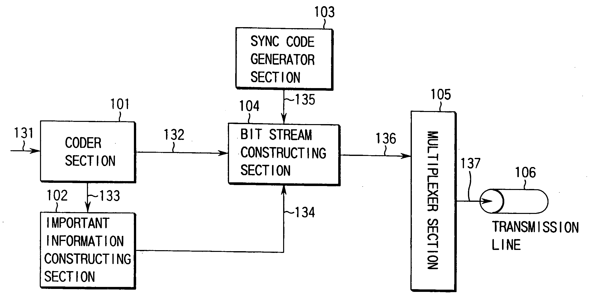
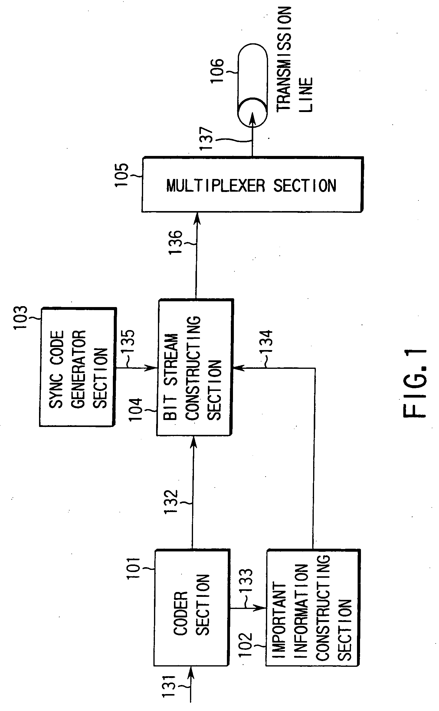
[0060]FIG. 1 shows the basic arrangement of a video coding apparatus according to the present invention. In FIG. 1, the output of a coder section 101 is connected to an important information constructing section 102 and bit stream reconstructing section 104. The output of the important information constructing section 102 is connected to the bit stream reconstructing section 104 together with the output of a sync signal generator section 103. The output of the bit stream reconstructing section 104 is connected to a multiplexer section 105. The output of the multiplexer section 105 is a transmission line 106.

[0061] The coder section 101 codes an input video signal 131 to output it to the bit stream reconstructing section 104, and outputs coded information 133 obtained by coding to the important information constructing section 102. The important information constructing section 102 receives the video signal 131 obtained by coding in the coder section 101, and selects and outputs only...

second embodiment

[0168] Another embodiment will be described as the

[0169]FIG. 10 is a block diagram showing the basic arrangement of a video coding apparatus according to the second embodiment of the present invention. In the video coding apparatus according shown in FIG. 10, the output of a coder section 601 is connected to a bit stream divider section 602 and important information constructing section 603. The output of the important information constructing section 603 is connected to a packet header generator section 604. The outputs of the bit stream divider section 602 and packet header generator section are connected to a packet structure section 605. The output of the packet structure section 605 is connected to a transmission line 106.

[0170] The coder section 601 codes an input video signal 131 to output it to the bit stream divider section 602, and outputs coded information 634 obtained by coding to the important information constructing section 102.

[0171] The important information const...

third embodiment

[0197] The important information construction section 705 as an important component in the third embodiment will be described in detail with reference to FIG. 15.

[0198] As shown in FIG. 15, the important information construction section 705 is made up of a switch section 2301, expansion header insertion determining section 2302, and arbitrary shape picture relating important information decoder section 2303.

[0199] The expansion header insertion determining section 2302 determines whether an expansion header is added to a packet header. The expansion header insertion determining section 2302 determines based on information of the packet header 735 input from the demultiplexing section 702 whether arbitrary shape picture coding is executed for the picture bit stream 732. If arbitrary shape picture coding is executed, the expansion header insertion determining section 2302 determines that an expansion header is added to a packet header, and outputs a control signal corresponding to th...


PUM


Abstract

A video coding apparatus includes a coder section 101 for coding an input video picture, an important information constructing section 102 for extracting important information from coded information obtained by the coder section, a sync signal generator section 103 for generating a sync signal, and a bit stream reconstructing section 104 for adding the sync signal output from the sync signal generator section and the important information reconstructed by the important information constructing section to the bit stream coded by the coder section, thereby reconstructing the bit stream.

Description

TECHNICAL FIELD [0001] The present invention relates to an information transmission scheme of transmitting a coded video picture / still picture using a cable communication network such as an ISDN (Integrated Services Digital Network) or Internet, or a radio communication network such as a PHS or satellite communication, and a coding / decoding apparatus in an information transmission system adopting this method. BACKGROUND ART [0002] Recently, with the advance of a digital coding technology and broadband network technology for various kinds of information such as a picture, applications using these technologies have extensively been developed. A system of transmitting a compression-coded picture and the like using a communication network is being developed. [0003] For example, a videophone, teleconference system, and digital television broadcast adopt a technique of compressing and coding video pictures and speech into small information amounts, multiplexing the compressed video code s...

Claims


Application Information

Patent Timeline
Patent Type & Authority Applications(United States)
IPC IPC(8): H04B1/66H04N11/02H04N11/04H04N7/12H04N19/89G06T9/00H04N7/26H04N7/50H04N7/52
CPCH04N21/23614H04N21/2365H04N21/2383H04N21/4348H04N19/20H04N19/70H04N19/46H04N19/61H04N19/89G06T9/20
Inventor NAGAI, TAKESHIKIKUCHI, YOSHIHIROMASUDA, TADAAKI
Owner NAGAI TAKESHI
Why Eureka
Try Eureka