Three-dimensional image processing apparatus, optical axis adjusting method, and optical axis adjustment supporting method

a technology of image processing apparatus and supporting method, which is applied in the direction of stereoscopic photography, camera body details, instruments, etc., can solve the problems of difficult adjustment of the direction of the optical axes of image processing apparatus, all the more difficult for users without expert knowledge of image processing, and no guarantee that the optical axis passes the center of the image pickup device. , to achieve the effect of high precision and adjustment of directions

Active Publication Date: 2006-01-12
ORMON CORP
View PDF1 Cites 23 Cited by
  • Summary
  • Abstract
  • Description
  • Claims
  • Application Information

AI Technical Summary

Benefits of technology

[0022] Thus, according to the present invention, even a person having no expert knowledge can adjust the directions of optical axes easily and with high precision.

Problems solved by technology

Although “crossing” has various advantages as described above, in reality, the optical axes are not seen, so that it is very difficult to adjust the directions of the optical axes of image capturing apparatuses.
It is all the more difficult for the user having no expert knowledge of image processing.
In the actual image capturing apparatus, however, there is no guarantee that the optical axis passes the center of the image pickup device due to mount variations of the image pickup device and an optical system (refer to FIG. 13).
Moreover, there is also the possibility that a deviation amount between the passing point of the optical axis in the image pickup device (the optical center of the image) and the center of the image pickup device (the center of the image) changes when the focal distance changes.
In the case where a center portion of an image does not include a characteristic image point and in the case where a similar pattern repeatedly appears in an image, erroneous correspondence between images may occur.
Therefore, the precision of optical axis adjustment in the conventional technique is limited.

Method used


Image

  • Three-dimensional image processing apparatus, optical axis adjusting method, and optical axis adjustment supporting method
  • Three-dimensional image processing apparatus, optical axis adjusting method, and optical axis adjustment supporting method
  • Three-dimensional image processing apparatus, optical axis adjusting method, and optical axis adjustment supporting method

Examples


first embodiment

(Configuration of Three-Dimensional Image Processing Apparatus)

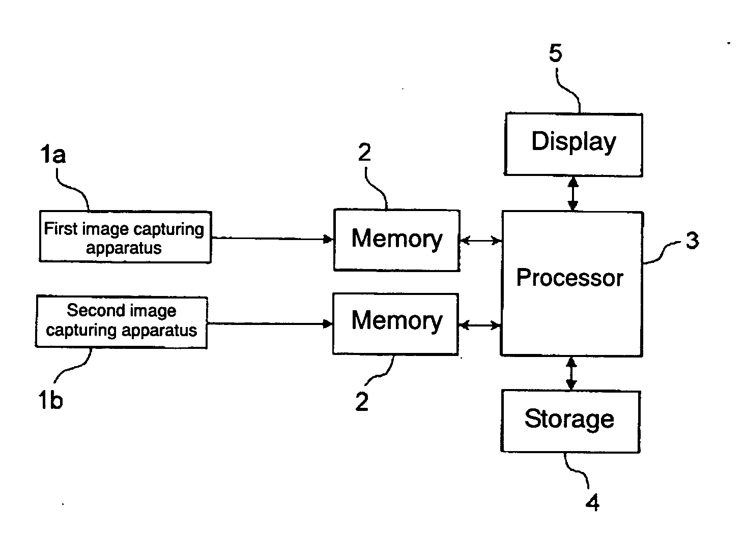
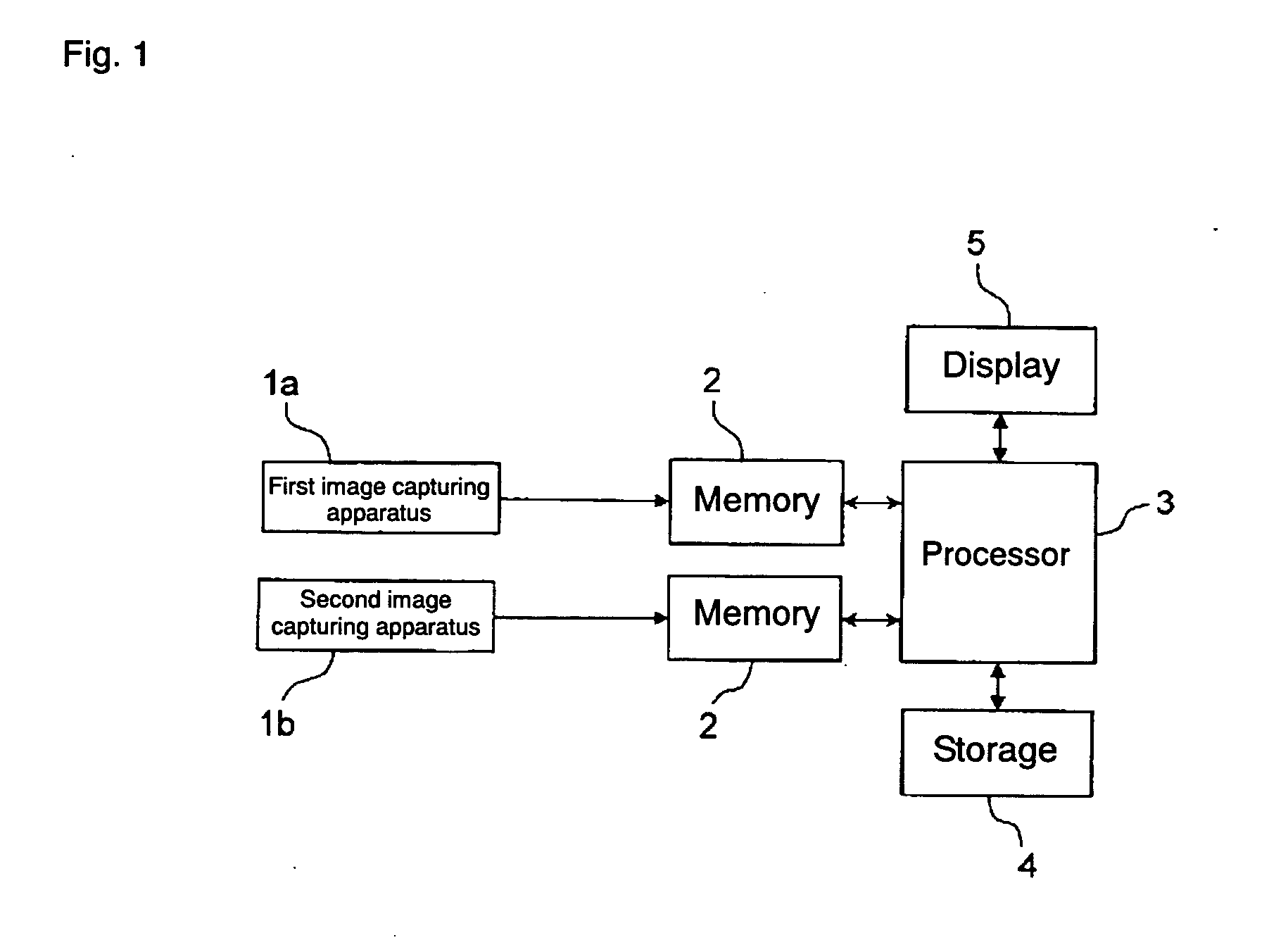
[0037]FIG. 1 shows a block diagram showing a hardware configuration of a three-dimensional image processing apparatus according to an embodiment of the present invention. The three-dimensional image processing apparatus includes, roughly, a first image capturing apparatus 1a, a second image capturing apparatus 1b, memories 2 and 2 for the image capturing apparatuses, a processor 3, a storage 4, and a display 5.

[0038] Each of the first and second image capturing apparatuses 1a and 1b (hereinbelow, also simply called “image capturing apparatus”) is an image capturing apparatus having an optical system constructed by plural lenses and an image pickup device constructed by a CCD, a CMOS, or the like. Digital images captured by the image capturing apparatuses 1a and 1b are temporarily stored in the memories 2 and, after that, input to the processor 3. The images captured by the image capturing apparatuses 1a and 1b may be ...

second embodiment

[0063] In a second embodiment of the present invention, a function of enlargedly displaying a portion including a mark is added. The other configuration is similar to that of the foregoing embodiment.

[0064] When an enlargement display function is executed in a state where the image of FIG. 6 is displayed on the display 5, the local areas around the marks 53 and 54 in the images 51 and 52 are enlargedly displayed (refer to FIG. 9). By the enlargement, the positioning between the marks and the points on the object 21 is facilitated and fine adjustment and matching of the optical axes can be performed with high precision.

[0065] In the case of digitally enlarging an image, it is sufficient to enlarge a local area in a display image by interpolation in the processor 3. In the case of optically enlarging an image, it is sufficient to increase the focal distance of the image capturing apparatuses 1a and 1b by sending a control signal from the processor 3. In this case, attention has to b...

third embodiment

[0066] In the case where the shape of an object is simple and easily recognized as shown in FIG. 6, the correspondence between the mark and the point on the object can be easily obtained. However, depending on the shape and pattern of an object, it is difficult to determine a point with which the mark is to be matched. There is a case that it is difficult to perform the optical axis adjustment by the method of the first embodiment.

[0067] In a third embodiment of the present invention, a function of superimposing marks of plural image capturing apparatuses on a single image is added. The other configuration is similar to that of the foregoing embodiments.

[0068] It is assumed that the image capturing apparatuses 1a and 1b and the reference plane 20 have the positional relations as shown in FIG. 10. In the diagram, a point C1 is the optical center of the first image 51, and a point C2 is the optical center of the second image 52. A point P1 is the meeting point of the optical axis L1...


PUM


Abstract

The present invention provides a technique for enabling even a person having no expert knowledge to adjust the direction of an optical axis easily with high precision. In a three-dimensional image processing apparatus having plural image capturing apparatuses, optical center of an image from an image capturing apparatus is stored for each of the image capturing apparatuses. A mark indicative of the optical center is superimposed on an image obtained from the image capturing apparatus. By referring to the mark for each of the image capturing apparatuses, the orientation of each of the image capturing apparatuses is adjusted so that all of the marks overlay on the same point on an object.

Description

BACKGROUND OF THE INVENTION [0001] 1. Field of the Invention [0002] The present invention relates to a three-dimensional image processing apparatus for obtaining three-dimensional information of an object from stereoscopic images captured by plural image capturing apparatuses and, more particularly, to a technique for adjusting directions of optical axes of the image capturing apparatuses. [0003] 2. Description of the Related Art [0004] One of the methods of obtaining three-dimensional information of an object from images is a method of capturing images of a predetermined image capture area by plural image capturing apparatuses disposed at predetermined intervals and obtaining corresponding relations of image formation points of the object on the captured plural images among the image capturing apparatuses. This method is generally called a stereo image process. [0005] In a three-dimensional image processing apparatus using the stereo image process, the optical axes of image capturi...

Claims


Application Information

Patent Timeline
Patent Type & Authority Applications(United States)
IPC IPC(8): G03B17/24G03B35/00H04N13/239
CPCG03B35/12G03B35/20H04N13/0296H04N13/0242H04N13/0239H04N13/243H04N13/296H04N13/239
Inventor SUWA, MASAKI
Owner ORMON CORP
Why Eureka
Try Eureka