

Dental instrument sharpening stone system
a technology for sharpening stones and dental instruments, applied in the field of dental instruments, can solve the problems of inability to sterilize the power sharpening system, inability to sharpen the tool, waste of time and motion,
- Summary
- Abstract
- Description
- Claims
- Application Information
AI Technical Summary
Benefits of technology
Problems solved by technology
Method used
Image

Examples
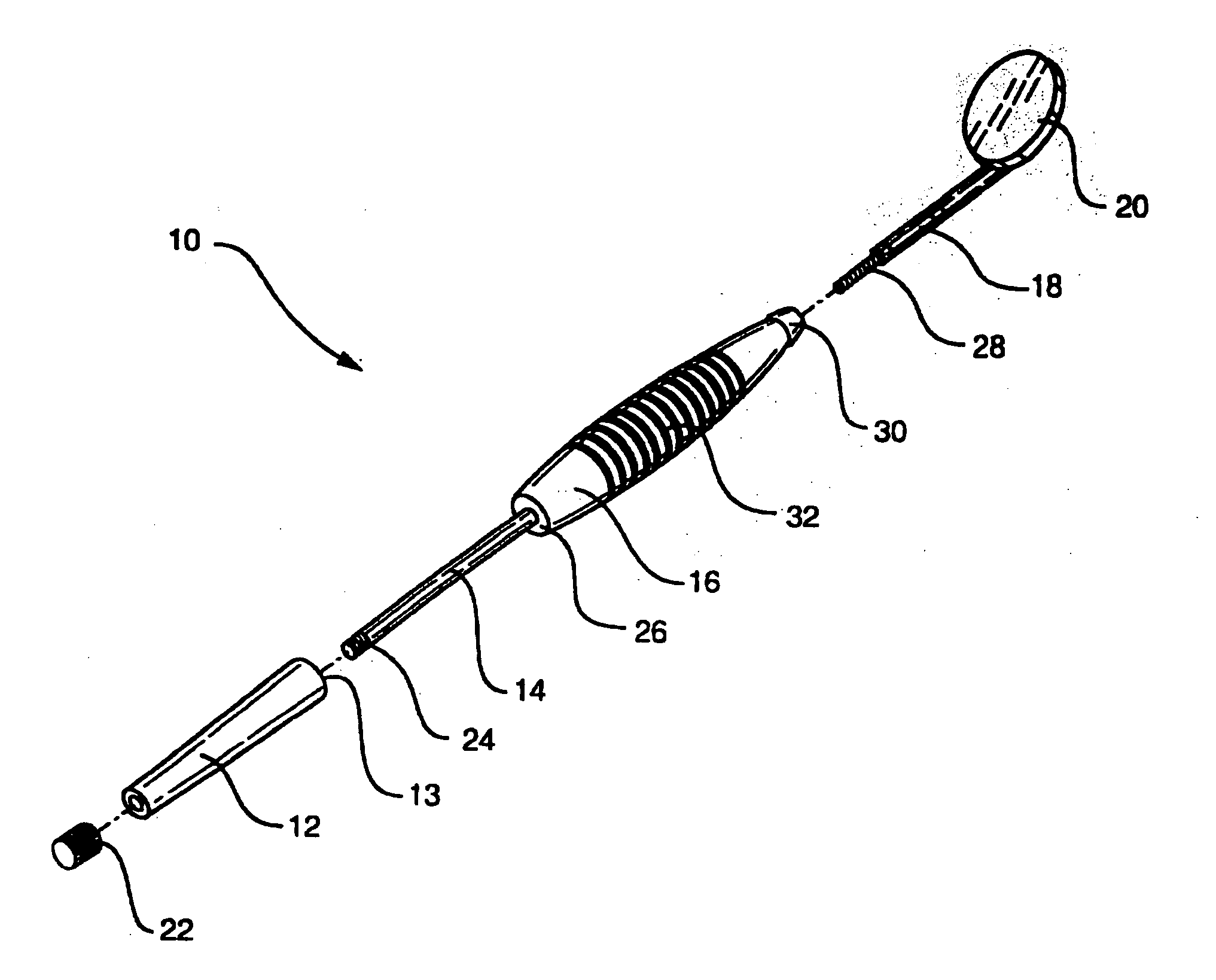
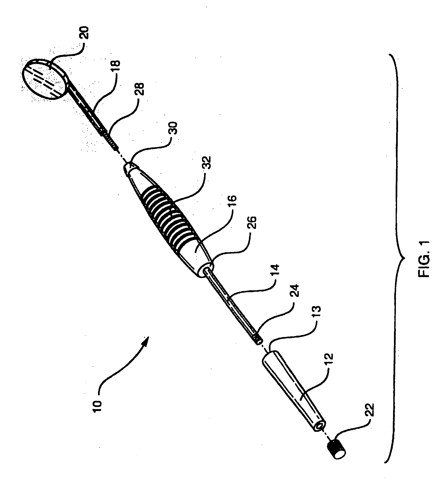
embodiment 10
[0024] The modular nature of embodiment 10 is not a limitation of the invention. However, this allows the instrument to be altered and customized as desired.
[0025]FIGS. 3 and 4 show second embodiment 50. This shows in a bit more detail the radial grooves 32 in grip 16 that are an alternative feature of this invention. Also shown is a different stone shape 52 that has two flat sides and two rounded sides.
embodiment 60
[0026]FIG. 5 shows similar embodiment 60 with stone 62 and washer 64. Washer 64 provides an elastic buffer between the stone and the handle. This provides a cushion to absorb stresses caused by differences in thermal expansion of the stone and the shaft when exposed to the high temperatures of steam autoclaving. The soft washer may also serve as a friction element to prevent inadvertent rotation of the stone relative to the grip.
embodiment 70
[0027] Embodiment 70, FIG. 6, illustrates alternative shapes of grip portion 74 having end 76, against which triangular-shaped sharpening stone 72 sits. This embodiment also illustrates another alternative feature of the invention to accomplish a guard where the stone meets the grip, which helps prevent the sharp curette tip from sliding onto the grip and cutting the hand. This is accomplished by making end portion 76 of grip 74 larger (i.e., located farther from the instrument shaft) than the matching end portion of the stone. This guard feature can be enhanced by enlarging or flaring end 76 of grip 74 as shown in the drawing, and / or by decreasing the radius of the stone.
Preferred Fabrication Options
[0028] Any common means of fabricating stones may be employed; including extruding, plating, molding, and casting. These means allow the forming of stones in many shapes, even complex shapes for the grip such as shown in FIG. 6. Naturally occurring abrasive stones such as Arkansas or ...
PUM
 Abstract
Description
Claims
Application Information