Optical sight with rangefinder and assembly method for the same

Inactive Publication Date: 2006-01-19
ASIA OPTICAL CO INC
View PDF19 Cites 21 Cited by
  • Summary
  • Abstract
  • Description
  • Claims
  • Application Information

AI Technical Summary

Benefits of technology

[0008] An object of the present invention is to provide an optical sight with rangefinder capable of easily facilitating adjustment during assem

Problems solved by technology

Understandingly, the assembly procedure of the conventional telescopic sig

Method used


Image

  • Optical sight with rangefinder and assembly method for the same
  • Optical sight with rangefinder and assembly method for the same
  • Optical sight with rangefinder and assembly method for the same

Examples


Embodiment Construction

[0031] The present invention will now be described more specifically with reference to the following embodiments. It is to be noted that the following description of the preferred embodiments of the present invention are presented herein for purpose of illustration and description only and it is not intended to be exhaustive or to be limited to the precise form disclosed.

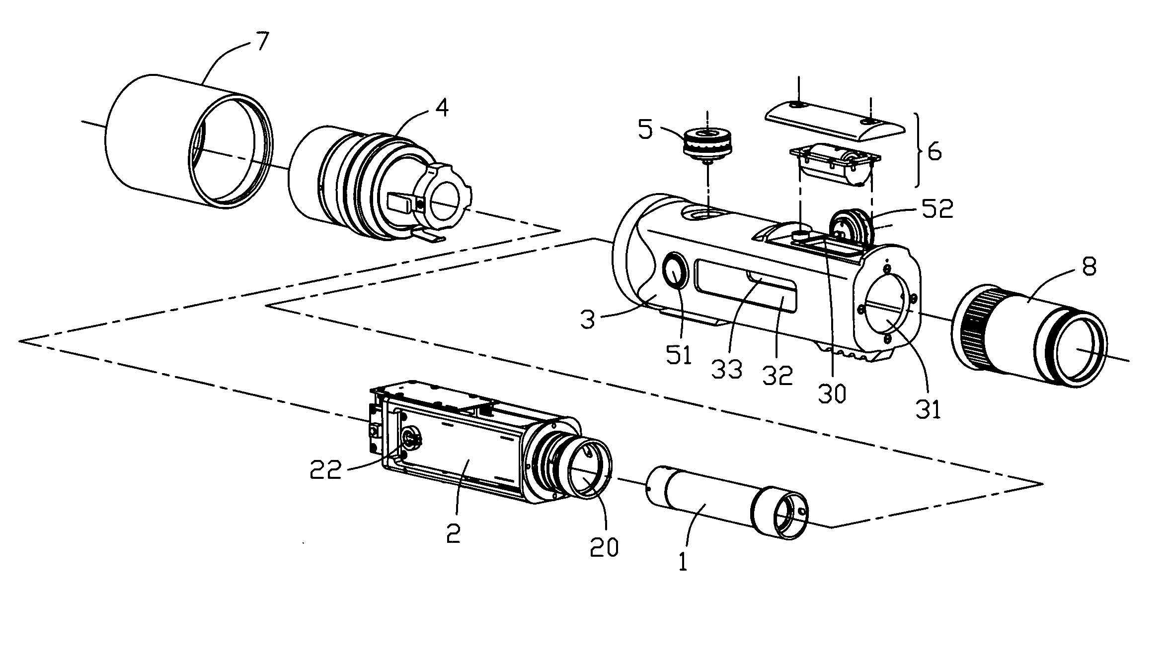
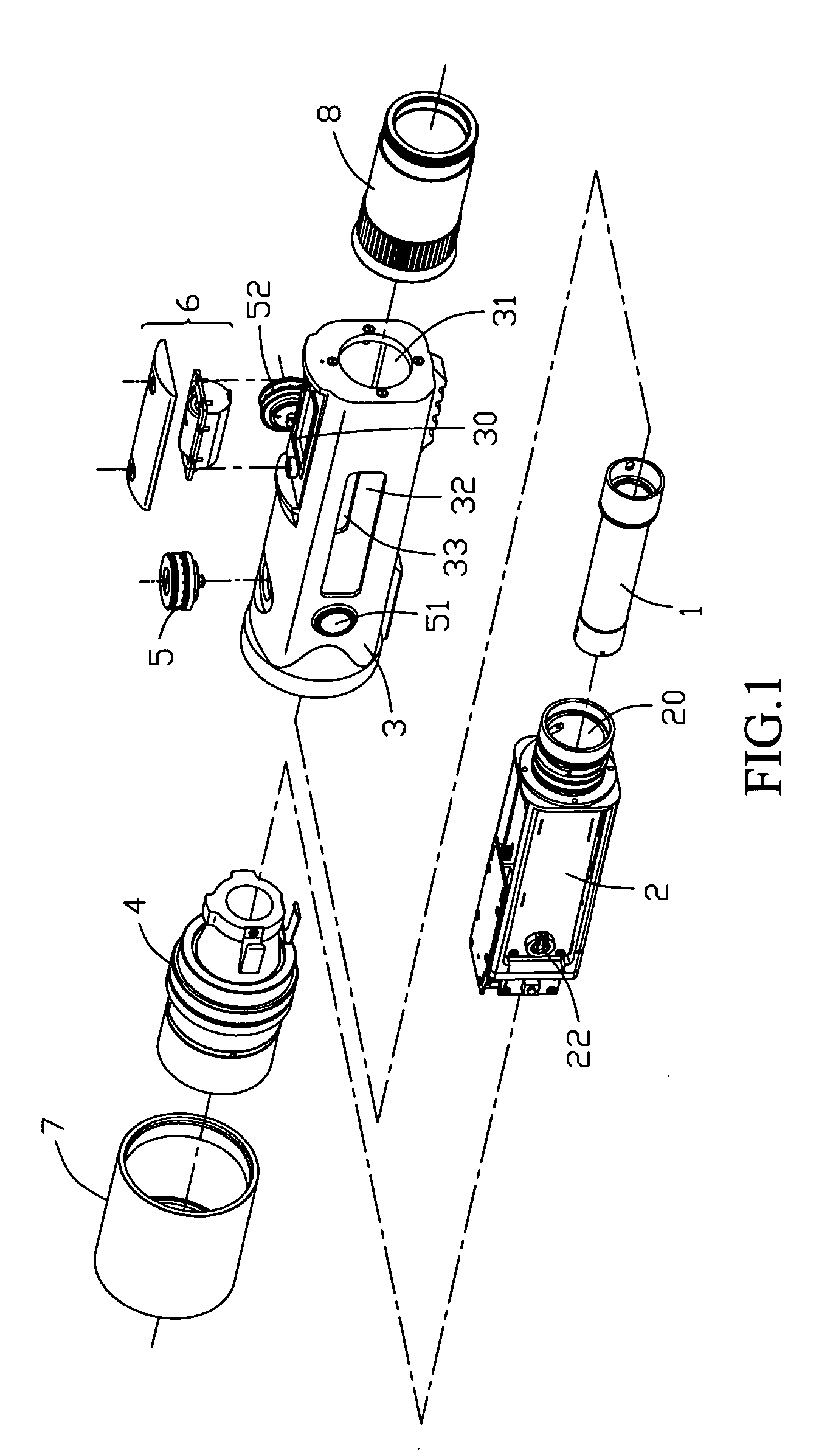
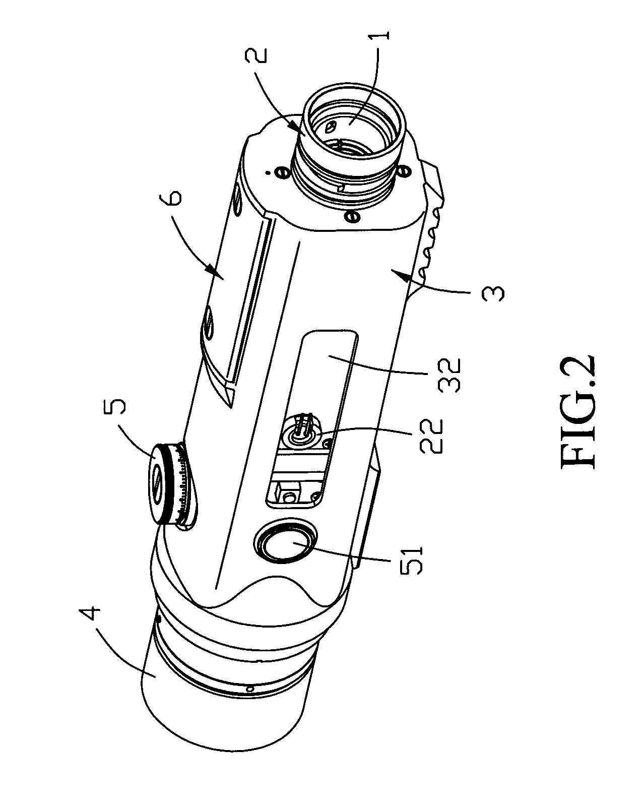
[0032] With reference to FIG. 1, a laser sight according to a preferred embodiment of the present invention, comprises an erector lens unit 1, a photoelectric rangefinding unit 2, a barrel 3, an objective lens unit 4, adjusting elements 5, 51, 52, a power supply unit 6 disposed on the barrel, an optical filter 7 and an eyepiece lens unit 8. The erector lens unit 1 is served to invert and revert the image produced by the objective lens into a normal way and capable of adjusting the magnification of the optical sight. A reticle served as a reference cross-hair mark for aiming a target is disposed within the erector l...


PUM


Abstract

The present invention provides an optical sight with rangefinder and assembly method thereof. The optical sight comprises an erector lens unit, a photoelectric rangefinding unit, a barrel, an objective lens unit, a plurality of adjusting elements, a power supply unit and an eyepiece lens unit disposed on the barrel. The photoelectric rangefinding unit includes a laser emitter, a laser receiver and a range indicator. A plurality of openings are formed on sidewall of the barrel corresponding to the positions of the laser emitter, laser receiver and range indicator for conducting the cavity to outside the barrel. The assembly method comprises the steps of: assembling the erector lens unit, the photoelectric rangefinding unit and the barrel together, then connecting an objective lens unit and mounting a plurality of adjusting elements, adjusting the objective lens unit and mounting the adjusting elements and the power supply unit, adjusting the focus of the laser emitter and the laser receiver and adjusting the position of the range indicator through the openings formed on the barrel for complying with the requirement of photoelectric rangefinding performance. The assembly method of the optical sight according to the present invention can be adjusted after all elements are assembled. The assembly method of the optical sight according to the present invention can be used to reduce the adjusting times and prevent unnecessary disassemblies and re-assemblies for simplifying the assembly process and improving the yield rate and the productibility of the optical sight.

Description

BACKGROUND OF THE INVENTION [0001] 1. Field of the Invention [0002] The present invention relates to an optical sight and assembly method for the same, and more specifically, to a telescopic optical sight capable of rangefinding and assembly method for the same. [0003] 2. The Related Art [0004] In general, an optical system of conventional telescopic sight comprises an objective lens assembly, an erector lens assembly, an eyepiece lens assembly and a scale board with a reticle. The scale board is marked with a rough rangefinding scale. A shooter can rapidly estimate the range to a target by referring to the rangefinding scale. Therefore, such conventional telescopic sight may be used as a simple rangefinder. [0005] However, the range estimation of conventional telescopic sight is mostly depended on the user's experience that may likely bring a larger tolerance. Accordingly, a telescopic sight progressively takes the precise shooting and rangefinding fields. A conventional telescopic...

Claims


Application Information

Patent Timeline
IPC IPC(8): F41G1/00
CPCF41G1/38
Inventor LIN, CHEN-YEHLIANG, SHANG-YUNG
Owner ASIA OPTICAL CO INC
Why Eureka
Try Eureka