Method for the prevention of deposits in steam systems

a technology for steam systems and deposits, applied in the direction of machines/engines, jet propulsion plants, hot gas positive displacement engine plants, etc., can solve the problems of reducing the performance of plants and requiring inspections with corresponding shutdown periods of plants

Inactive Publication Date: 2006-01-19
ALSTOM TECH LTD
View PDF4 Cites 2 Cited by
  • Summary
  • Abstract
  • Description
  • Claims
  • Application Information

AI Technical Summary

Benefits of technology

[0013] The object on which the invention is based, therefore, is to make available a method for preventing the deposition of impurities in steam systems, in which method the disadvantages of the prior art are avoided.
[0015] The essence of the invention, therefore, is not, as hitherto according to the prior art, to bring the quality, that is to say the purity, of the steam to a specific very low value preventing deposits with high probability, but, instead, under the conditions given in practice for the steam quality and according to the solubility behavior of the impurities, to prevent a situation where a separation of the impurities in a steam system can occur at all. To be precise, it becomes clear, surprisingly, that the total “prepurification” of the water or of the steam is not actually necessary at all, but that it is sufficient to avoid critical parameters being reached in the steam system, that is to say to avoid steam parameters which entail a separation of impurities.
[0016] This is carried out in that, by a suitable choice of the design parameters and / or by an appropriate routing of the steam in the system, or, if appropriate, by appropriately ensuring the temperature, the temperature and pressure parameters never assume values which make a separation of impurities possible. In other words, it is crucial to prevent an excessive lowering of temperature and / or pressure to a critically low value. This may take place in many different ways, either by preventing a critical lowering of the temperature by an increase in the steam mass flow and / or by a reduction in cooling external influences and / or else also by the steam experiencing a corresponding temperature increase, particularly in critical regions of the steam system. Influence can be exerted on the pressure in that, by the type and configuration of steam routing in the steam system, the flow conditions are designed in such a way that pressure losses, particularly in critical regions, are avoided.
[0019] Moreover, as an additional measure for the prevention of deposits, there may be provision for the temperature and / or pressure of the steam flowing in the steam system to be set in such a way that the steam solubility of the impurities present in a specific concentration in the steam is not exceeded in the steam system. The latitude for the temperature and / or pressure parameters of the steam flowing in steam systems is usually sufficient to reduce even further the risk of deposits by a specific selection or optimization of at least one of these parameters.
[0020] The method can be organized in a particularly advantageous way in that both values are monitored simultaneously and the pair of values, namely the pressure and temperature of the steam in the steam system, never assumes a critical value, and in that particularly critical regions of the steam system with significant pressure drops are avoided. In particular, this may also be carried out in that a lowering of the pressure such that the steam solubility of the impurities present in specific concentrations in the steam would be exceeded is compensated by means of a corresponding rise in the temperature.
[0022] A further exemplary embodiment of the invention is characterized in that the sole critical pressure drop in the steam system is placed at the outlet point of the steam from the device for the use of steam. Thus, deposits will occur at most in the outlet region which is easy to clean. If, moreover, the flow velocities of the steam are high at the outlet point, a self-cleaning effect may be established.

Problems solved by technology

Without this purity, deposits occur within the steam systems, the performance of the plants is diminished and inspections with corresponding shutdown periods of the plants become necessary.
This results, not least for the steam generator technology employed, in numerous constraints, for example with regard to component design (steam drying in drums and separators), steam temperature regulation by water injection or steam mixing, the chemical operating modes, etc.

Method used


Image

  • Method for the prevention of deposits in steam systems
  • Method for the prevention of deposits in steam systems
  • Method for the prevention of deposits in steam systems

Examples


Embodiment Construction

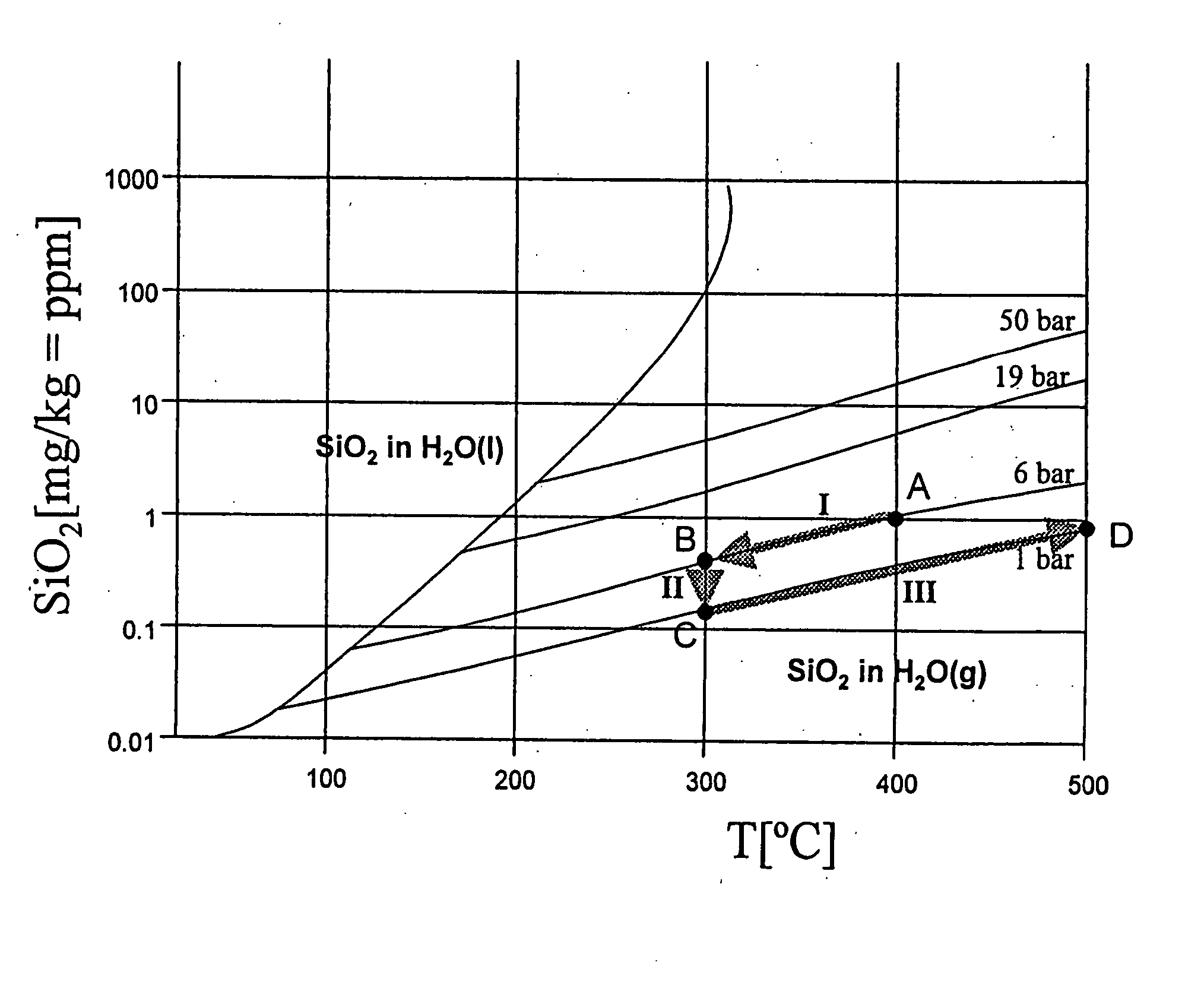
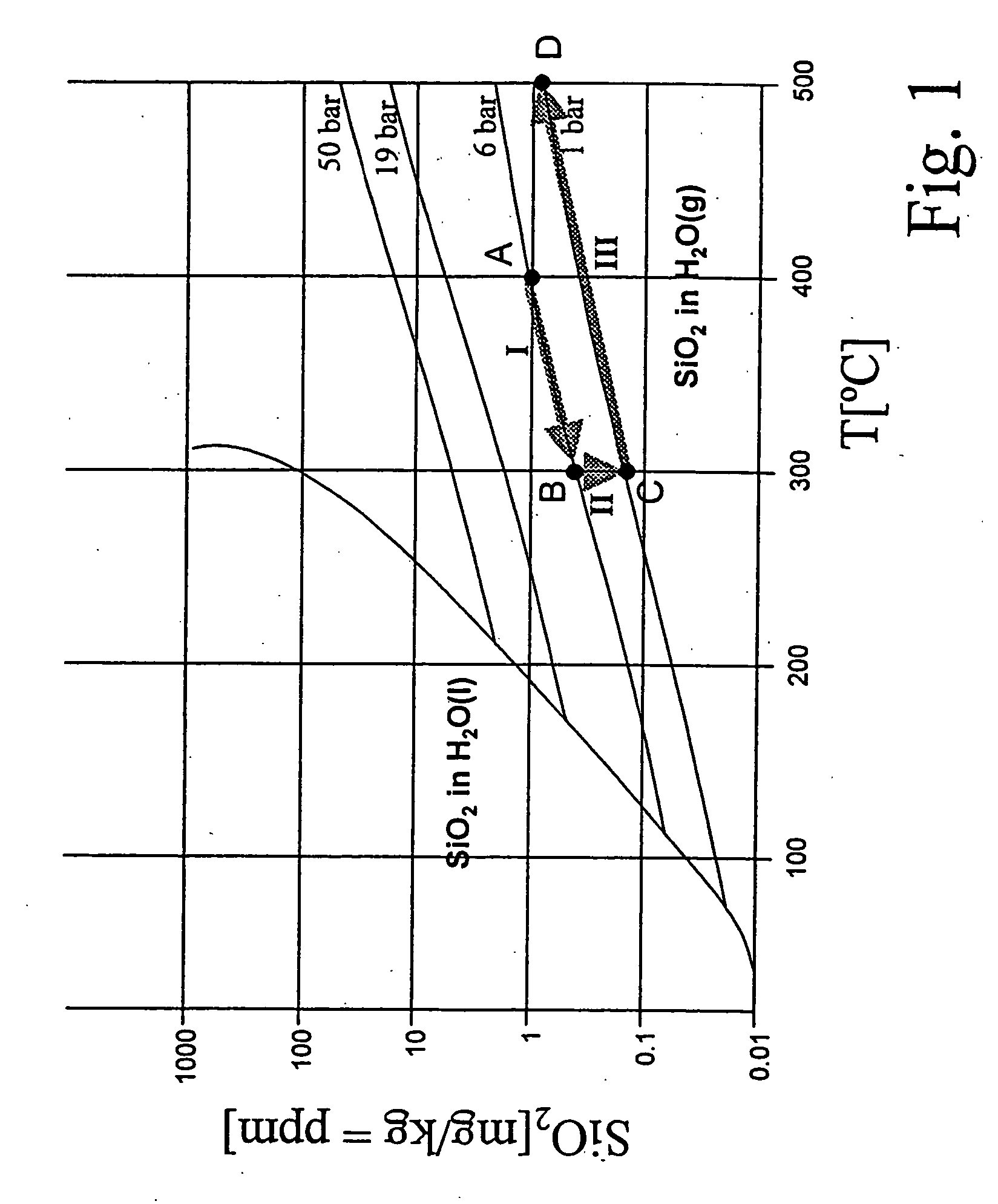
[0028] The steam solubility of impurities depends essentially on the pressure and temperature parameters. In general, with a rise in temperature and a rise in pressure, their steam solubility rises and vice versa, the pressure influence being dominant. FIG. 1 shows by way of example for all impurities a diagram for the solubility of SiO2 in water or steam as a function of the temperature at pressures of 1 bar, 6 bar, 19 bar and 50 bar. It is clear that, for a pressure of 6 bar and a temperature of 400° C., SiO2 is soluble in steam up to a concentration of approximately 1 mg / kg (1000 ppb).

[0029] In spite of this behavior which is known per se, for the prevention of deposits in steam systems, it has hitherto always been concluded that only by ensuring the conditions corresponding to the most unfavorable case and therefore by the lowest concentration of SiO2 or of another impurity is it possible for a deposition of this to be effectively prevented. Thus, to avoid SiO2 deposits in stea...


PUM


Abstract

In a method for preventing the deposition of impurities in steam systems, in which steam of a given steam quality flowing in them is subject to temperature and / or pressure changes, a simple prevention of deposits is achieved in that an appropriate structural configuration and design of the steam systems prevents the steam solubility of the impurities present in specific concentrations in the steam from being exceeded as a result of changes in the temperature and / or pressure conditions.

Description

FIELD OF THE INVENTION [0001] The present invention relates to a method for preventing the deposition of impurities in steam systems, in which the steam of a given steam quality flowing in them is subjected to temperature and / or pressure changes. The invention also relates to a steam system for carrying out the method. BACKGROUND OF THE INVENTION [0002] For the cooling of components subjected to high thermal load in energy machines, for example a gas turbine plant, it is intended, for reasons of efficiency, to make increasing use of steam as a coolant. This steam can flow as steam, but also as a steam / air mixture, in an open, semi-open or closed system through the components to be cooled. [0003] In an open steam system, the steam is led from a device for the provision of steam (waste-heat boiler, steam turbine plant, auxiliary steam generator, etc.) to the device for the use of steam, for example a gas turbine plant, in order to cool the components of the latter while being heated. ...

Claims


Application Information

Patent Timeline
Patent Type & Authority Applications(United States)
IPC IPC(8): F02C3/30F01K21/06
CPCF01K21/06
Inventor LIEBIG, ERHARDSVOBODA, ROBERT
Owner ALSTOM TECH LTD
Why Eureka
Try Eureka