Refrigeration system

a refrigeration system and refrigeration technology, applied in the field of refrigeration systems, can solve the problems of not being able to evaporate all liquid, affecting the efficiency of compressors, so as to increase the system cop, reduce the loss of the system to the external environment, and increase the specific cooling capacity.

Active Publication Date: 2006-01-19
ANHUI WATERPOWER ENERGY SAVING TECH
View PDF54 Cites 38 Cited by
  • Summary
  • Abstract
  • Description
  • Claims
  • Application Information

AI Technical Summary

Benefits of technology

[0009] In this arrangement, the expansion device comprises a conduit whose wall provides a heat exchange surface so that, for example, refrigerant flowing through the expansion conduit to an evaporator of the refrigeration system can exchange heat with refrigerant flowing from the evaporator to a compressor. Positioning the expansion conduit within an enclosure in the accumulator chamber at least partially isolates the expansion conduit from liquid refrigerant in the accumulator chamber and allows refrigerant flowing through the conduit to exchange heat predominantly with gaseous and / or two-phase refrigerant received from the evaporator of the refrigeration system. This arrangement both obviates the need for a separate expansion device, thereby allowing the refrigeration system to be more compact, and promotes a heat exchange process which assists in preventing liquid refrigerant flowing into the compressor. This arrangement also reduces the evaporation of liquid refrigerant in the accumulator so that more liquid is available in the evaporator, thereby increasing the efficiency and cooling capacity of the refrigeration system. As the system does not depend on any heat exchange with liquid refrigerant in the accumulator, the present arrangement is particularly suitable for use with transcritical refrigerants such as CO2 in which liquefaction of the refrigerant is more difficult than other more conventional refrigerants.
[0039] In accordance with embodiments of the present invention, the high temperature refrigerant from the high pressure side is sub-cooled to lower temperatures on passage through the expansion conduit, and the expansion conduit simultaneously effects expansion of the refrigerant to a lower quality (liquid richer) state, compared with conventional cycles for the introduction into the evaporator. In addition, this brings vaporous refrigerant generated in the evaporator or in the accumulator-expander-heat exchanger to a higher quality or even a superheated gaseous state for return to the compressor, which will increase the COP of compressor.

Problems solved by technology

At low heat loads in certain working conditions it is not possible to evaporate all the liquid.
However, a large amount of liquid is undesirable because system efficiency could be lowered and the compressor could be significantly damaged if a large amount of liquid refrigerant enters the compressor (known as “liquid slugging”).
In these systems, for refrigerants with relatively low critical temperatures, e.g. carbon dioxide which has a critical temperature of 31.7° C., it is difficult to reach a high specific cooling capacity and this is a significant barrier for achieving a high coefficient of performance (COP).
However, in U.S. Pat. No. 6,530,230, an expansion device is simply assembled at the inlet of accumulator-heat exchanger without being functionally integrated.
However, those explorations focus only on subcritical refrigerants.
This will not increase the specific cooling capacity, and the extra circulating refrigerant needed will consume more energy.
As a result, the whole system performance might not be improved significantly.
Furthermore, the heat gain from environment between the evaporator outlet and the inlet of compressor (including accumulator) will decrease the system COP.

Method used


Image

  • Refrigeration system
  • Refrigeration system
  • Refrigeration system

Examples


Embodiment Construction

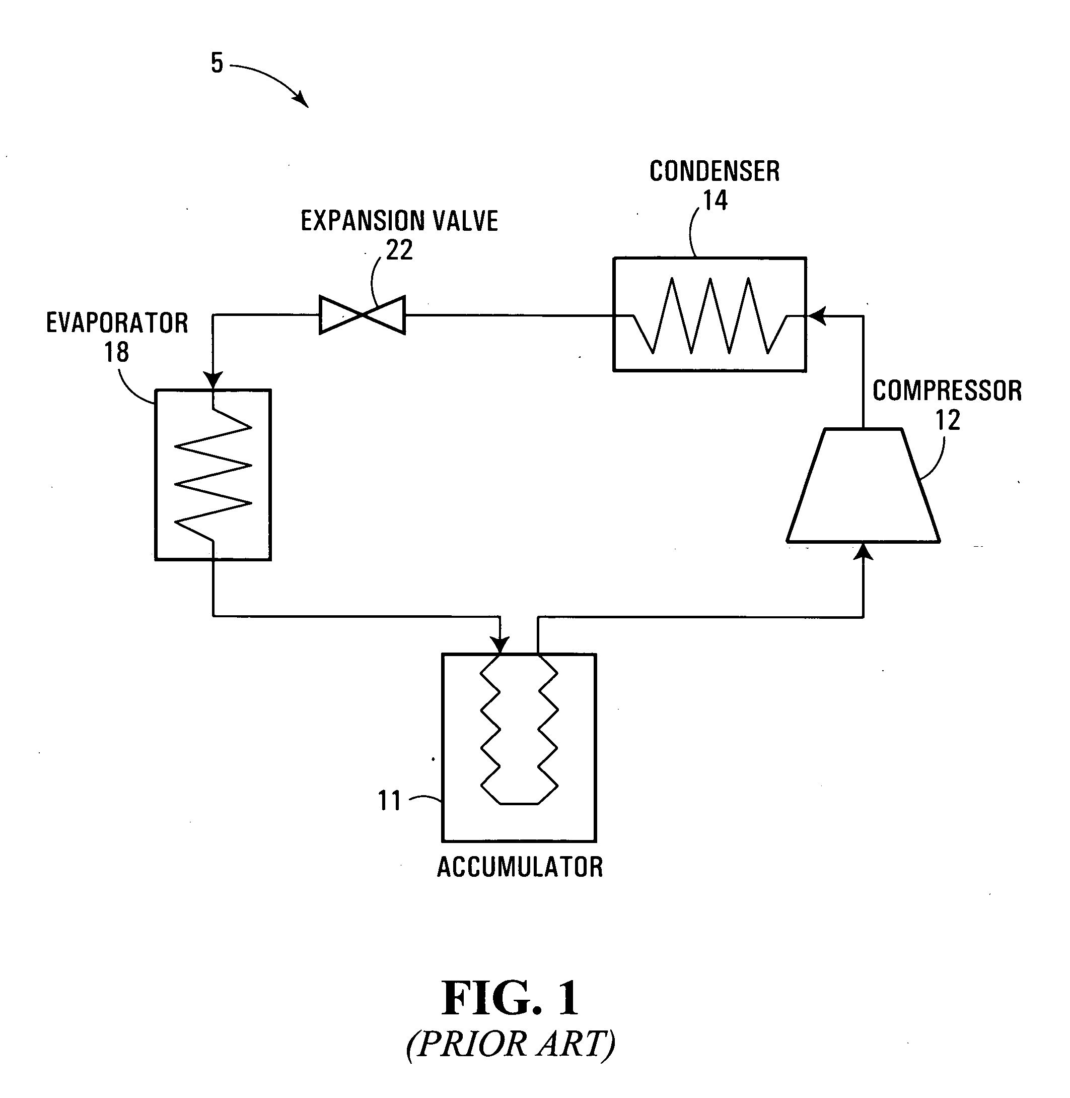
[0054] In a conventional air-conditioning system 5 of FIG. 1, liquid refrigerant is stored in an accumulator 11 to be drawn in gaseous-liquid two-phase form to the inlet of a compressor 12. The compressor 12 delivers high temperature—high pressure refrigerant gas (i.e. substantially higher than ambient) to a condenser / gas cooler 14 where the gas is cooled and / or typically partially converted to a liquid form. Refrigerant fluid from the condenser 14 (still under high pressure) is expanded to a lower pressure through an expansion device 22, thereby undergoing a rapid drop in temperature; the low temperature low pressure fluid is then evaporated in an evaporator 18 from where it is returned to the accumulator 11 in a mixed flow of liquid and gas. Depending upon the loading of the system, more or less refrigerant fluid is condensed and evaporated; refrigerant that is in excess of the instantaneous requirements of the system is stored in liquid form in the accumulator 11. The compressor,...


PUM


Abstract

A refrigeration system with integrated accumulator-expander-heat exchanger is disclosed. Refrigerant from a condenser / gas cooler is throttled through a capillary tube while at the same time undergoing a heat exchanging process with refrigerant from an evaporator. This method can elevate the compressor efficiency, increase the specific cooling capacity, and enhance the system performance. The capillary tube, which has dual functions of expansion device and heat exchanger, is placed inside a canister which also functions as an accumulator. The new device combining three separate parts into one can simplify the manufacturing process, lower the system size and weight, and thus decrease cost of the whole system.

Description

CROSS-REFERENCE TO RELATED APPLICATIONS [0001] This application claims priority from U.S. Provisional Patent Application No. 60 / 586,297 filed on Jul. 9th, 2004.FIELD OF THE INVENTION [0002] The present invention relates generally to refrigeration systems with a heat exchanger, and more particularly but not limited to transcritical systems used in automobile vehicles, e.g. in the form of CO2 air conditioners. BACKGROUND OF THE INVENTION [0003] Closed-loop refrigeration / heat pump systems conventionally employ a compressor that is meant to draw in vaporous refrigerant at relatively low pressure and discharges hot refrigerant at relatively high pressure. The hot refrigerant is then cooled in a gas cooler if the pressure and temperature are higher than values of temperature and pressure at the critical point, otherwise it condenses into liquid, and the gas cooler is called condenser accordingly. “Critical point” is a physical property of pure substances defined by temperature and pressur...

Claims


Application Information

Patent Timeline
Patent Type & Authority Applications(United States)
IPC IPC(8): F25B43/00F25B41/00
CPCF25B9/008F25B40/00F25B41/06F25B41/067F25B43/006F28D7/14F25B2341/0662F25B2400/051F25B2400/052F28D7/024F25B2309/061F25B41/37F25B41/39
Inventor GU, JUNJIE
Owner ANHUI WATERPOWER ENERGY SAVING TECH
Why Eureka
Try Eureka