
Apparatus for detecting hunting and angle of attack of a rail vehicle wheelset

a technology for detecting angle of attack and wheelet, which is applied in vehicle tyre testing, instruments, roads, etc., can solve the problems of easy damage to cargo, and rapid wear of truck and vehicle components, so as to achieve accurate, rugged, easy to install and maintain

Active Publication Date: 2006-01-19
WABTEC CONTROL SYST PTY LTD
View PDF16 Cites 23 Cited by
  • Summary
  • Abstract
  • Description
  • Claims
  • Application Information

AI Technical Summary

Benefits of technology

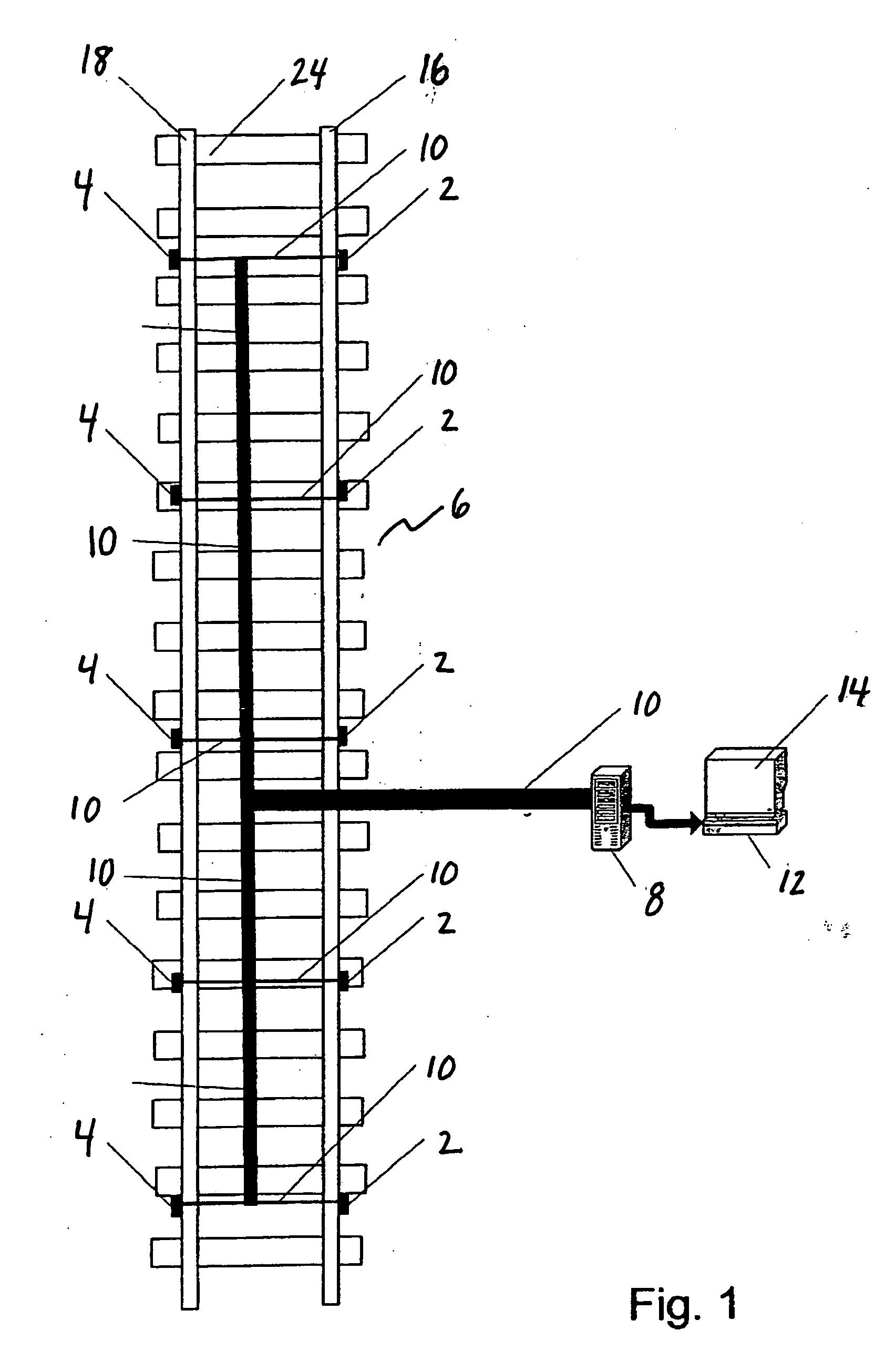
[0011] The following disclosure describes an apparatus and method for measuring angle of attack of individual wheels and wheelsets, as well as trucks and rail vehicles, that is accurate, rugged, and easy to install and maintain. It is thus one aspect of the present invention to provide an apparatus and method for both measuring angle of attack and detecting hunting of individual wheels on each rail as well as wheelsets, trucks and railway vehicles. It is a further aspect of the present invention to provide a rail mounted system to allow measurement of angle of attack and detection of hunting for all wheels and wheelsets of a railway vehicle. In one embodiment, the invention employs sensors to determine both angle of attack and lateral position of each wheelset to detect hunting of a wheelset, truck or railway vehicle. More specifically, in one embodiment, the apparatus comprises multiple pairs of sensors, a first sensor of each pair interconnected to a first rail and a second sensor of each pair interconnected to a second rail, to estimate the angle of attack of each wheel of each wheelset at various points along each rail and to compare the angle of attack at those various points to determine whether any wheelset, truck or railway vehicle is hunting.
[0013] It is a further aspect of the present invention to use sensors that do not require significant changes to a railway during installation and are rugged and easy to maintain. It is thus one aspect of the present invention to utilize sensors that are suitable for installation on any track at practically any location along the rails of the track. Further, in one embodiment, the present invention does not require significant changes to rail infrastructure or supplementation by other devices. More specifically, in one embodiment, the present invention employs sensors adjacent to the rails.
[0015] It is an additional aspect of the present invention to calculate both angle of attack and lateral position of each wheel on multiple wheelsets to more accurately detect hunting. Further, in one embodiment of the present invention, basic reliable engineering principles are used to derive the angle of attack and the lateral position of each wheelset to determine hunting and tracking of each wheelset.

Problems solved by technology

Hunting may be caused by worn truck components, wear or defects in the track or rails or a variety of other reasons.
Hunting results in rapid wear of truck and vehicle components, rails and other railway components, and has the potential to cause damage to cargo and perhaps eventually lead to derailment.
The detection of hunting is important but relatively difficult.
As such, a hunting condition may go undetected for a substantial period of time.
However, a positive angle of attack indicates a potential for a wheel set, truck or railway vehicle to climb the rails and even derail.
Further, a positive angle of attack has the potential to generate transverse forces that may result in damage to railway and truck components and increase costs of maintenance and repair of such components.
Such truck-mounted systems, however, are not suitable for use at a way station or a wayside, i.e., along the side or edge of a railroad track.
Further, such truck-mounted systems are unsuitable for detecting hunting of individual wheels or wheelsets or measuring angle of attack of wheels, wheelsets, trucks or railway vehicles.
Such vehicle-mounted systems are typically mounted to a particular wheelset, and therefore, are unsuitable for way station or wayside use or for determining angle of attack for all wheelsets on a railway vehicle.
Further, because such systems are located on the vehicles themselves, the systems are less reliable and require more maintenance and supervision than a system suitable for way station or wayside use.
The known wayside systems and methods for measuring angle of attack, however, are spaced substantially from the track and result in a static measurement which does not take into account dynamic misalignment of the rails due to train forces, environmental forces such as moisture and temperature changes, or misalignment of the wayside measuring systems due to the same or similar environmental forces.
In addition, such systems are located to one side of the track making it unsuitable for directly detecting the angle of attack of wheels on the far rail.
Further, laser beam systems are expensive, require continued maintenance and supervision and are prone to misalignment and malfunction due to the often treacherous railway environment and other moving objects associated with the environment.
Such systems, however, involve multiple types of gages to detect a number of forces and strain and require expensive and time consuming changes to track infrastructure or supplementation by other devices.
Further, as rail sections are changed out, the potential loss of strain gages makes strain gage technology impractical.
Further, known strain gage systems require precise location and installation of the gages, a time consuming and tedious process.
For example, strain gages must be precisely located on a rail and often cannot be placed over a tieplate or sleeper as rail flexure needed to measure strain occurs between the sleepers.
Moreover, the accuracy of strain gages may be compromised by temperature, material properties, the adhesive that bonds the gages to a rail, and the stability of the railway metal.
For example, many strain gage materials are sensitive to changes in temperature and tend to drift and change resistance as they age.
Further, calculating angle of attack based significantly on measurements of strain requires complex calculations.

Method used


Image

  • Apparatus for detecting hunting and angle of attack of a rail vehicle wheelset
  • Apparatus for detecting hunting and angle of attack of a rail vehicle wheelset
  • Apparatus for detecting hunting and angle of attack of a rail vehicle wheelset

Examples


Embodiment Construction

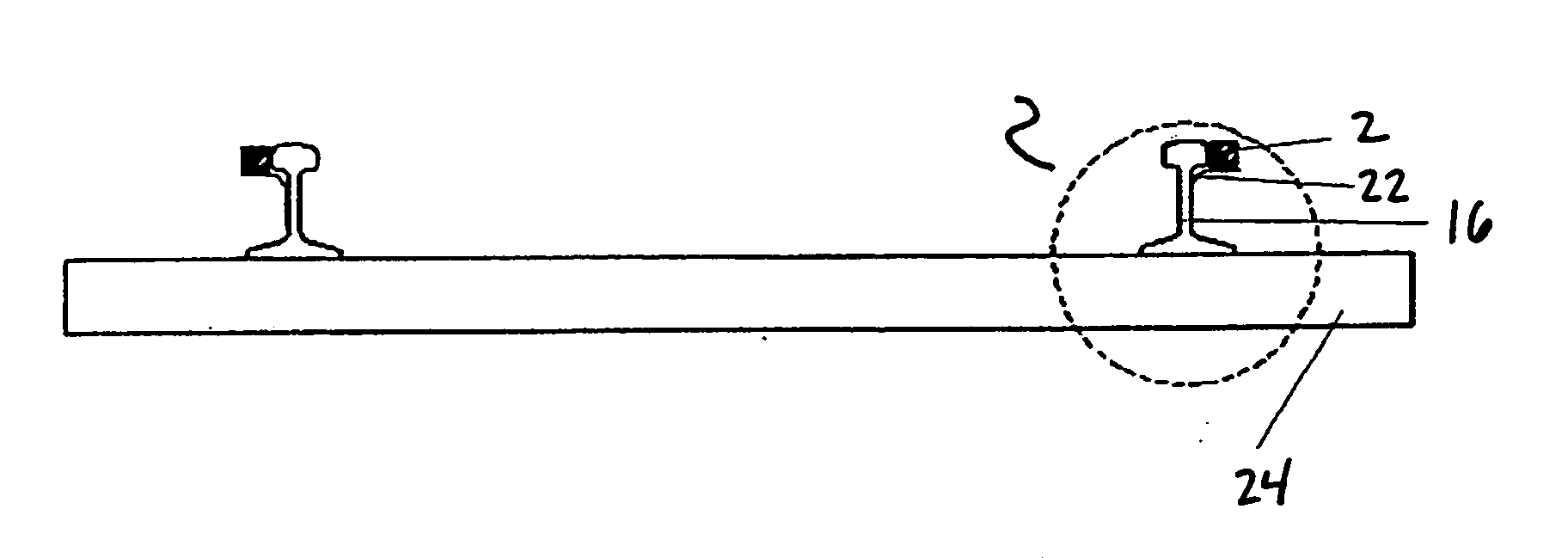
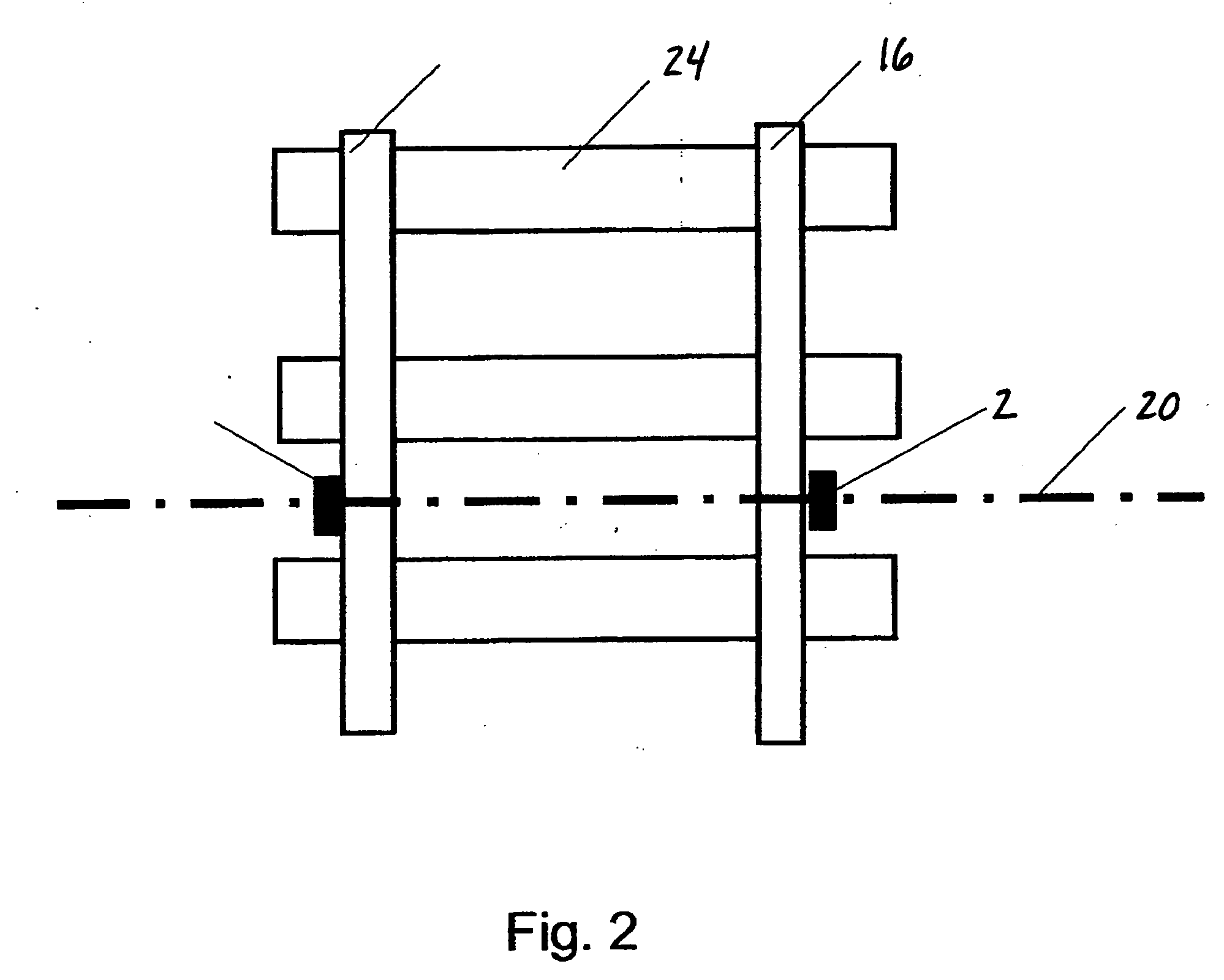
[0031] Referring now to FIG. 1, an overall apparatus schematic top plan view of one embodiment of the present invention is set forth. In one embodiment, at least one first sensor 2 and at least one second sensor 4 are positioned along a railway 6 and arranged in a manner that enables output of each first sensor 2 and each second sensor 4 to be communicated to, recorded, processed and / or displayed by a sensor monitoring unit 8. In one embodiment, the sensor monitoring unit 8 is associated with a power source and power and signal cables 10, which operably interconnect each first sensor 2 and each second sensor 4 to the sensor monitoring unit 8. The sensor monitoring unit 8 may include digital signal processors or other devices for data storage, transfer, timing and communication of the sensors to the sensor monitoring unit 8.

[0032] The sensor monitoring unit 8 may also be in communication with a central processing unit 12. In one embodiment, information from the sensor monitoring uni...


PUM


Abstract

An apparatus and method for estimating the angle of attack of wheels, wheelsets, trucks and railway vehicles traveling over a track employing a wayside system having a plurality of sensors, adjacent to the rails of the track, for detecting the passing of each wheelset of each truck. Each sensor communicates its moment of activation and length of activation caused by a passing wheel to a sensor monitoring unit for use in determining the angle of attack of the passing wheel, wheelset, truck and railway vehicle. The estimated angle of attack of the wheelset at different locations along the track may be used to detect a hunting wheelset, truck or railway vehicle.

Description

CROSS REFERENCE TO RELATED APPLICATION [0001] This application claims the benefit, under 35 U.S.C. Section 119(e), to U.S. Provisional Application Ser. No. 60 / 588,910, filed Jul. 16, 2004, the entirety of which is hereby expressly incorporated by reference herein.FIELD OF THE INVENTION [0002] The present invention relates generally to an apparatus and method for measuring angle of attack of a wheelset and detecting wheelset, truck and rail vehicle hunting. More particularly, the present invention relates to a system and method for detecting hunting and measuring angle of attack of a wheelset of a rail car traveling on a rail employing sensors that detect the proximity of moving objects. BACKGROUND OF THE INVENTION [0003] Hunting is a condition in which a wheelset, truck or rail vehicle oscillates from side to side between rails of track while moving. Hunting may be caused by worn truck components, wear or defects in the track or rails or a variety of other reasons. Hunting results i...

Claims


Application Information

Patent Timeline
Patent Type & Authority Applications(United States)
IPC IPC(8): G01M17/02
CPCB61L1/04G01M17/10G01M17/08G01M17/013
Inventor KILIAN, KRZYSZTOFMAZUR, VLADIMIRRANWALA, HILARY GRATION
Owner WABTEC CONTROL SYST PTY LTD
Learn More