Electromagnetic missile launcher

a technology of electromagnetic and missile launcher, which is applied in the field of missile launcher, can solve the problems of increasing the risk of attack, affecting the ability of the missile launcher to perform routine tasks, and affecting the ability of the missile to exit the engine, so as to avoid some of the costs and disadvantages

Inactive Publication Date: 2006-01-19
MARTIN LOCKHEED
View PDF17 Cites 17 Cited by
  • Summary
  • Abstract
  • Description
  • Claims
  • Application Information

AI Technical Summary

Benefits of technology

[0005] The present invention provides a technique for launching a missile that avoids some of the costs and disadvantages for doing so in the prior art. In particular, the illustrative embodiment of the present invention uses an electromagnetic catapult to throw the missile clear of the launch platform—with sufficient velocity to attain aerodynamic flight—before the missile's engine is ignited. This mitigates some of the problems associated with launching missiles in the prior art.

Problems solved by technology

When a missile is launched, the discharge of the hot gases causes several problems.
First, the hot gases heat the launch platform, which renders the launch platform more visible to enemy infrared sensors and, therefore, more vulnerable to attack.
Second, the hot gases can obscure the ability of personnel in the area of the launch platform to see, which might impair their ability to perform routine tasks, such as detecting enemy threats.
Third, the brightness of the flame exiting the engine can—especially at night—temporarily blind the personnel in the area of the launch platform.
Fourth, the missile's fuel often comprises an aluminized compound that is dispersed in the atmosphere surrounding the launch platform, which can impair the operation of radar systems near the launch platform.
And fifth, as modern missiles become larger, their gases become hotter and more voluminous, and, therefore, cannot be adequately vented within the launching platform using current technology.

Method used


Image

  • Electromagnetic missile launcher
  • Electromagnetic missile launcher
  • Electromagnetic missile launcher

Examples


Embodiment Construction

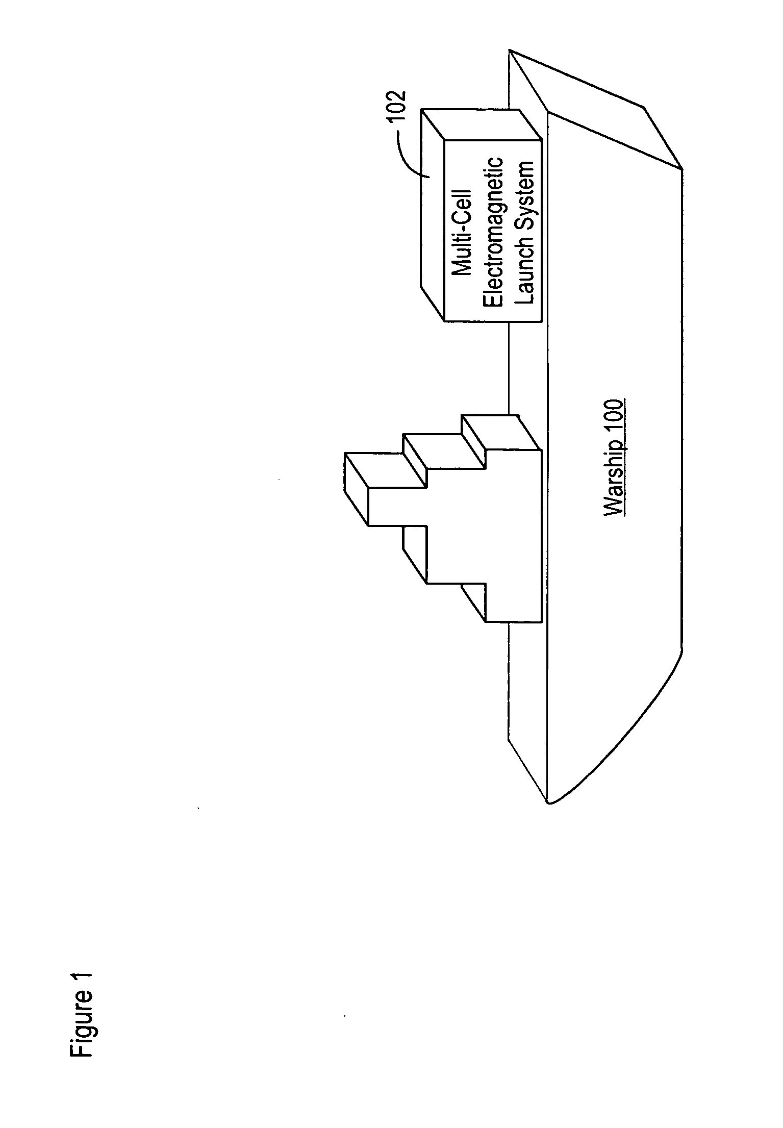
[0018]FIG. 1 depicts a representational diagram of a naval launch system in accordance with the illustrative embodiment. Although launch system 102 is mounted on the deck of a warship, it will be clear to those skilled in the art, after reading this disclosure, how to make and use alternative embodiments of the present invention in which launch system 102 is terrestrially-based or is mounted on another type of vehicle (e.g., a truck, a railroad car, a submarine, a space vehicle, a satellite, etc.)

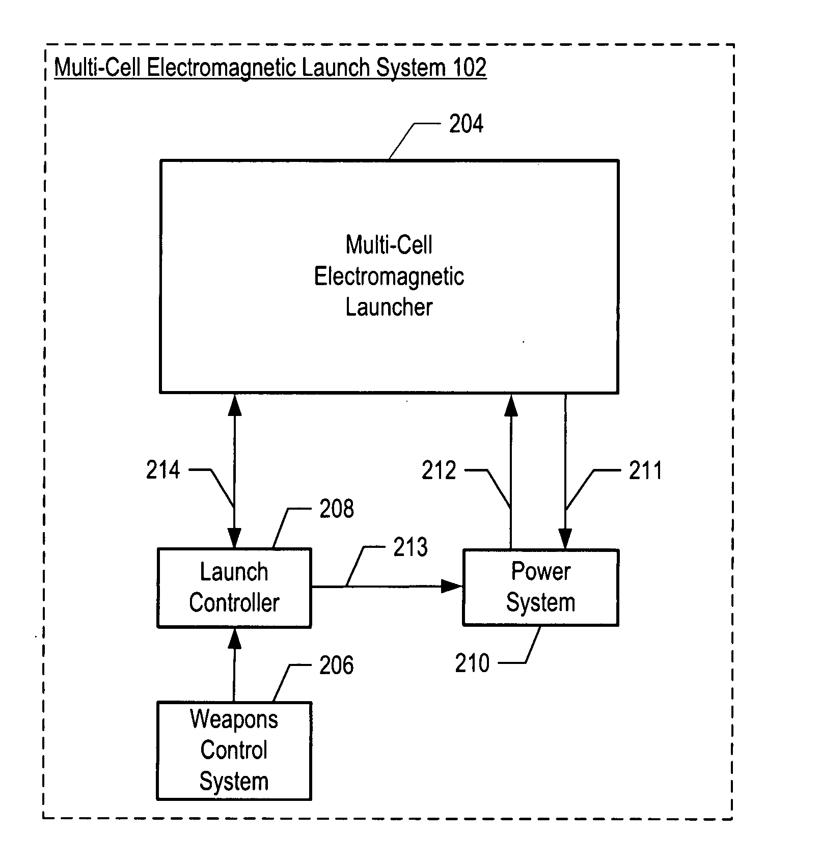
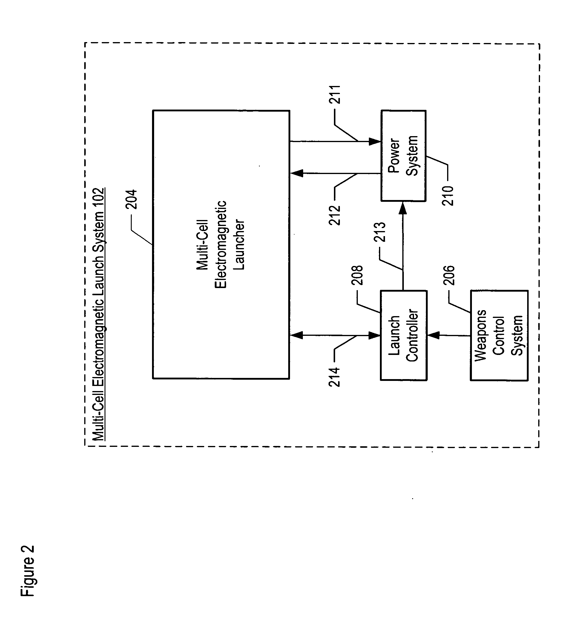
[0019]FIG. 2 depicts a schematic diagram of the salient components of launch system 102. Launch system 102 comprises multi-cell electro-magnetic launcher 204, weapons control system 206, launch controller 208, power system 210, return power bus 211, propulsion current bus 212, signal line 213, and data bus 214.

[0020] Launcher 204 is a system that has the capability to house and expel one or more missiles upon command. The system expels each missile from its cell using an electromagnetic c...


PUM


Abstract

A technique for launching a missile that avoids some of the costs and disadvantages for doing so in the prior art. In particular, the illustrative embodiment of the present invention uses an electromagnetic catapult to throw the missile clear of the launch platform—with sufficient velocity to attain aerodynamic flight—before the missile's engine is ignited.

Description

FIELD OF THE INVENTION [0001] The present invention relates to missilery in general, and, more particularly, to missile launchers. BACKGROUND OF THE INVENTION [0002] A missile is propelled by fuel and a chemical-propulsion engine. A chemical-propulsion engine propels a missile by the reaction that results from the rearward discharge of gases that are liberated when the fuel is burned. For the purposes of this specification, a “missile” is defined as a projectile whose trajectory is not necessarily ballistic and can be altered during flight (as by a target-seeking radar device and control elements). [0003] When a missile is launched, the discharge of the hot gases causes several problems. First, the hot gases heat the launch platform, which renders the launch platform more visible to enemy infrared sensors and, therefore, more vulnerable to attack. Second, the hot gases can obscure the ability of personnel in the area of the launch platform to see, which might impair their ability to...

Claims


Application Information

Patent Timeline
Patent Type & Authority Applications(United States)
IPC IPC(8): F41F5/00F41B6/00
CPCF41B6/003F42B6/006
Inventor ROOT, GEORGE RAYMOND JR.
Owner MARTIN LOCKHEED
Why Eureka
Try Eureka