Quick release for article handling mechanism

a technology of article handling and quick release, which is applied in the direction of instruments, curtain suspension devices, de-stacking articles, etc., can solve the problems of faulty or failed dispensing/vending operation, and achieve the effect of easy determination of changes and more toleran

Inactive Publication Date: 2006-01-19
CHIRNOMAS MUNROE
View PDF15 Cites 8 Cited by
  • Summary
  • Abstract
  • Description
  • Claims
  • Application Information

AI Technical Summary

Benefits of technology

[0018] Although use of an airflow sensor is described in the preferred embodiment, it is intended that a vacuum sensor coupled to the hose so to sense changes in the partial pressure inside the hose, is a further embodiment in place of, or even in addition to, the described airflow sensor. However, some of the advantages of an airflow sensor in the present embodiment are that it has more tolerance and is more accepting of power and vacuum fluctuations. Rather than determining vacuum at a preset level, which may require a more delicate measuring apparatus, the airflow sensor more easily determines changes in relatively small amounts of airflow in the hose.

Problems solved by technology

When the control mechanism of the dispenser has determined normal operation, the time of the occurrence of the airflow signal can be used by the control mechanism to confirm that the article has been properly moved, for example from the storage area to a dispensing area, but if the sensed airflow signal has been determined by the control mechanism to be premature (because the signal from the airflow sensor occurred before the hose positioner moved the hose to a predetermined dispensing position), it's occurrence indicates a faulty or failed dispensing / vend operation.

Method used


Image

  • Quick release for article handling mechanism
  • Quick release for article handling mechanism
  • Quick release for article handling mechanism

Examples


Embodiment Construction

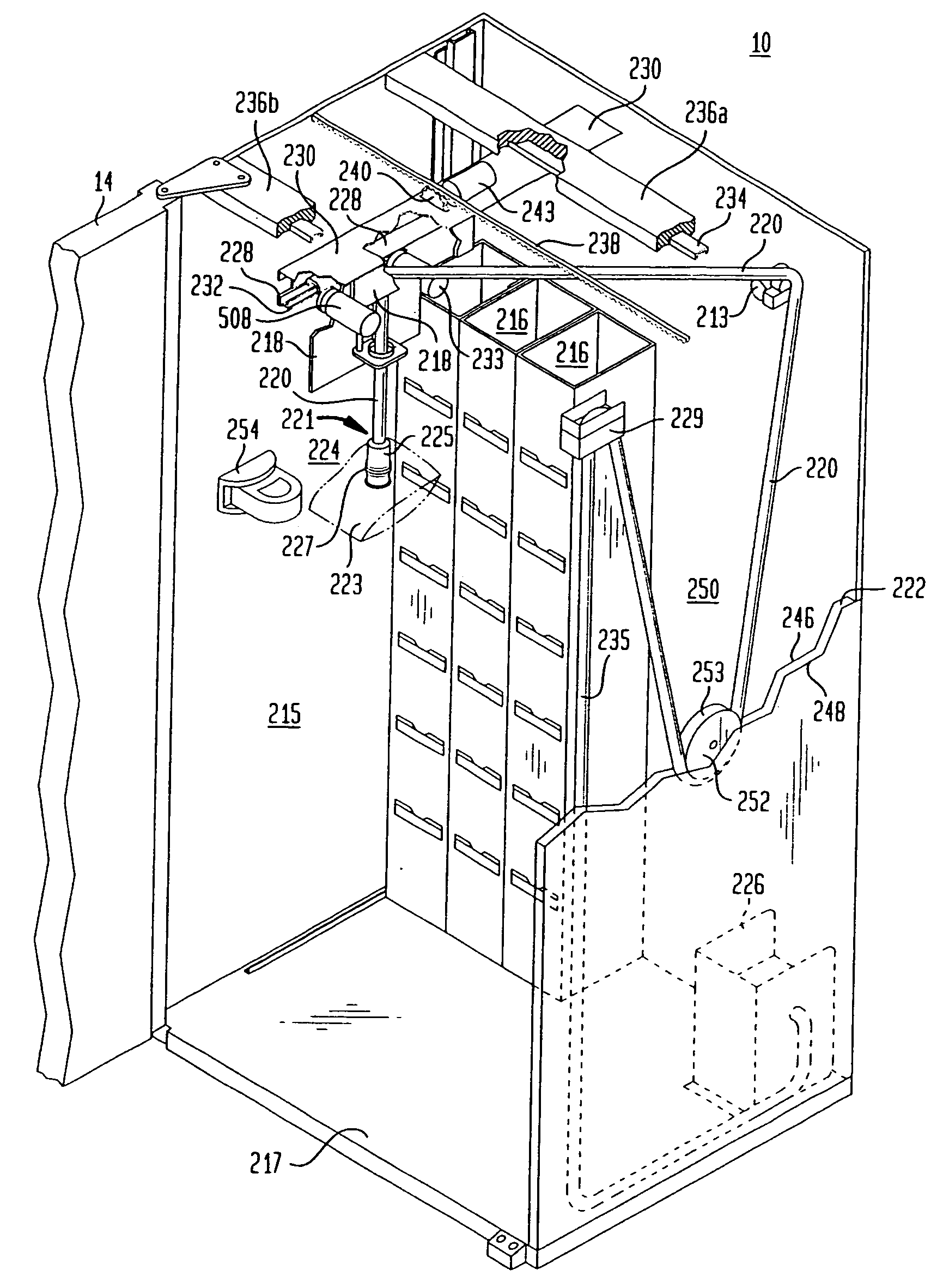
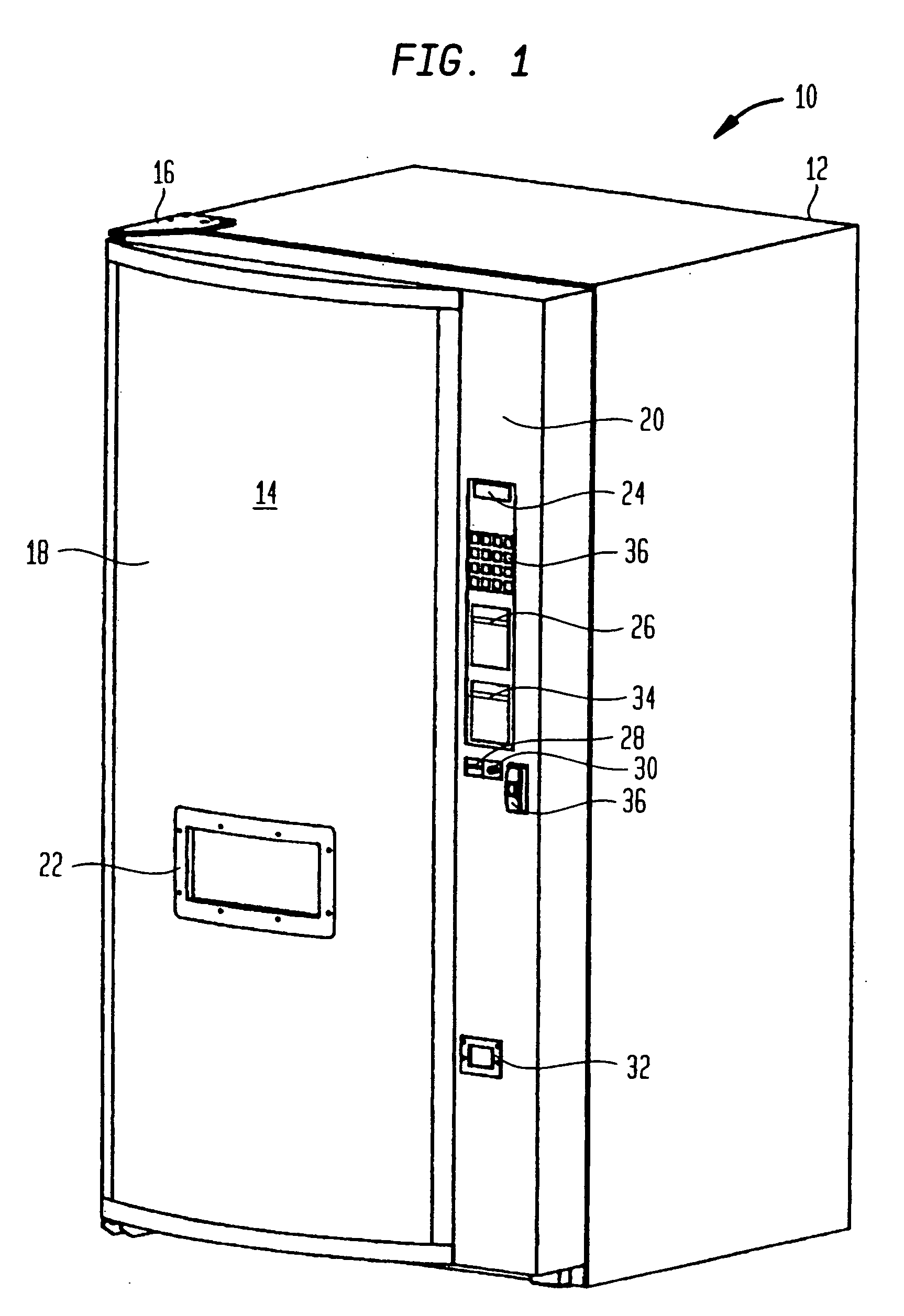
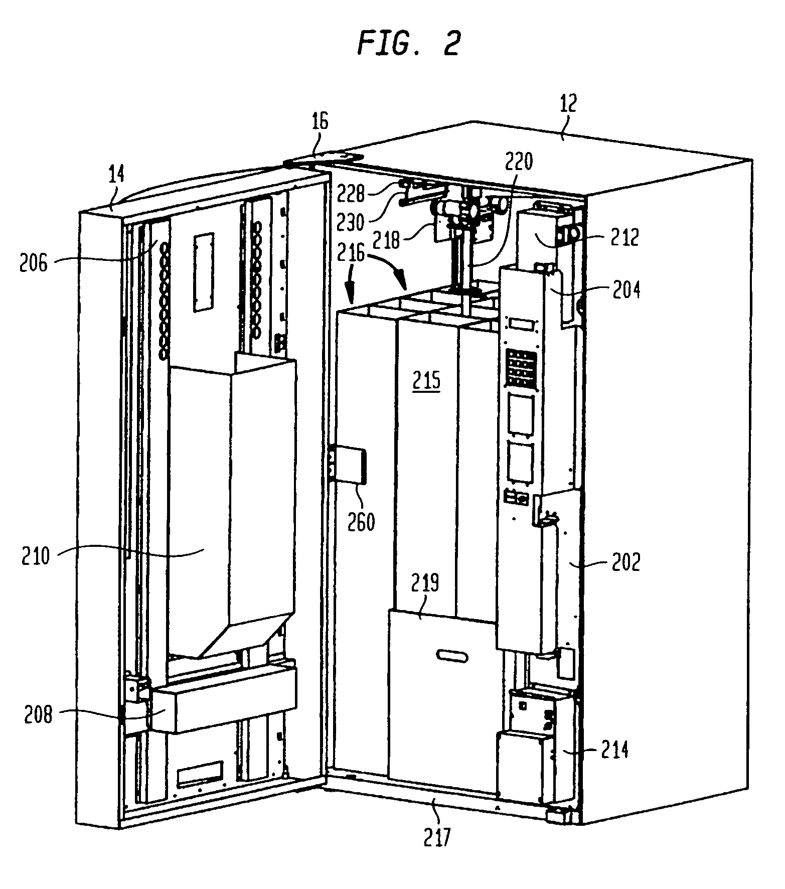
[0023]FIG. 1 illustrates an environment for the invention described herein, in the form of an article dispenser, such as a point-of-sale (POS) dispenser. Although throughout the following description, reference is made to implementation of the invention in a vending machine environment, it is intended that the term “vending machine”, and in fact the environment for the present invention, include more general purpose article handling, retrieval and / or dispensing apparatus, as well as POS equipment. Such equipment, if embodied as a portable device may comprise and be about the size of a traditional vending machine or as large as a tractor-pulled trailer, and if embodied as a non-portable device may comprise and be embodied as an automated dispensing room or an area located in a permanent structure, such as in a building (aboveground or underground, and with or without interior walls or an enclosing cabinet). Furthermore, it is intended that the term “articles” or “products” include in...


PUM


Abstract

An article dispensing apparatus, such as a vending machine (10), includes a controllably positioned suction hose dispenser (220) for retrieving articles (223) from a storage area (215). In one embodiment, a quick release device (500) coupled to the suction hose dispenser (220), is activated in response to mechanical contact caused by the controllable positioning of the suction hose dispenser (220), said activation facilitating a quick release of the retrieved article to a place (210) associated with an article dispensing area (22).

Description

CROSS-REFERENCE TO RELATED APPLICATIONS [0001] This application is a continuation application of and claims priority under 35 USC 120 of U.S. application Ser. No. 10 / 875,485, filed Jun. 24, 2004, now U.S. Pat. No. 6,942,122 issued Sep. 13, 2005, which itself is a continuation of and claims priority under 35 USC 120 of U.S. application Ser. No. 10 / 296,528, filed Nov. 23, 2002, now U.S. Pat. No. 6,786,355, which is a U.S. national phase designation of PCT application PCT / US01 / 16,916 filed May 23, 2001, the contents of which applications and patents are expressly incorporated herein by this reference thereto.BACKGROUND OF THE INVENTION [0002] 1. Field of the Invention [0003] The present invention relates generally to improvements in the design and operation of article handling apparatus and is particularly useful in the environment of article handling devices that use a suction-type article handling mechanism. [0004] 2. Description of the Prior Art [0005] Most prior art article handlin...

Claims


Application Information

Patent Timeline
Patent Type & Authority Applications(United States)
IPC IPC(8): B23Q7/04B65G59/00
CPCG07F11/04G07F11/14G07F11/62G07F11/165G07F11/16G07F11/1657
Inventor CHIRNOMAS, MUNROE
Owner CHIRNOMAS MUNROE
Why Eureka
Try Eureka