
Synchronous amplitude modulation for improved performance of optical transmission systems

a technology of optical transmission system and synchronous amplitude, which is applied in the field of optical transmission of information, can solve the problems of system performance degradation, long optical fiber transmission path, and long transmission path, and achieve the effects of improving transmission performance, reducing system performance, and improving transmission performan

Inactive Publication Date: 2007-11-06
TYCO ELECTRONICS SUBSEA COMM LLC
View PDF30 Cites 9 Cited by
  • Summary
  • Abstract
  • Description
  • Claims
  • Application Information

AI Technical Summary

Benefits of technology

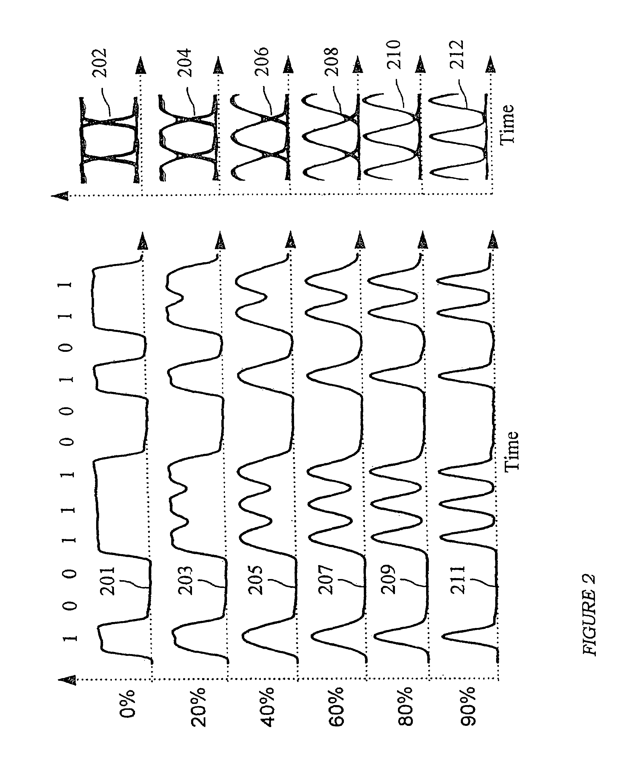
[0007]In accordance with the present invention, a method and apparatus is provided that yields improved performance of both single channel and WDM long-distance optical transmission systems by synchronously modulating of the transmitted signal's amplitude. An amplitude modulator receives an optical signal onto which data has been modulated at a predetermined frequency. The modulator re-modulates the amplitude of the optical signal in a continues fashion with a waveform that is periodic, whose fundamental frequency is equal to the same predetermined frequency at which the data is modulated onto the optical signal. The resulting signal (which is neither a pure NRZ or RZ signal) is more tolerant to the distortions usually found in lightwave transmission systems, thus giving superior transmission performance.

Problems solved by technology

Very long optical fiber transmission paths, such as those employed in undersea or transcontinental terrestrial lightwave transmission systems, which employ optical amplifier repeaters, are subject to decreased performance due to a host of impairments that accumulate along the length of the optical fiber comprising the transmission path.
Generally speaking, the impairments that limit the system's performance cause two types of degradations in the received eye pattern, which are related to randomness (caused by noise) and deterministic degradations (or distortions in the received bit pattern).

Method used


Image

  • Synchronous amplitude modulation for improved performance of optical transmission systems
  • Synchronous amplitude modulation for improved performance of optical transmission systems
  • Synchronous amplitude modulation for improved performance of optical transmission systems

Examples


Embodiment Construction

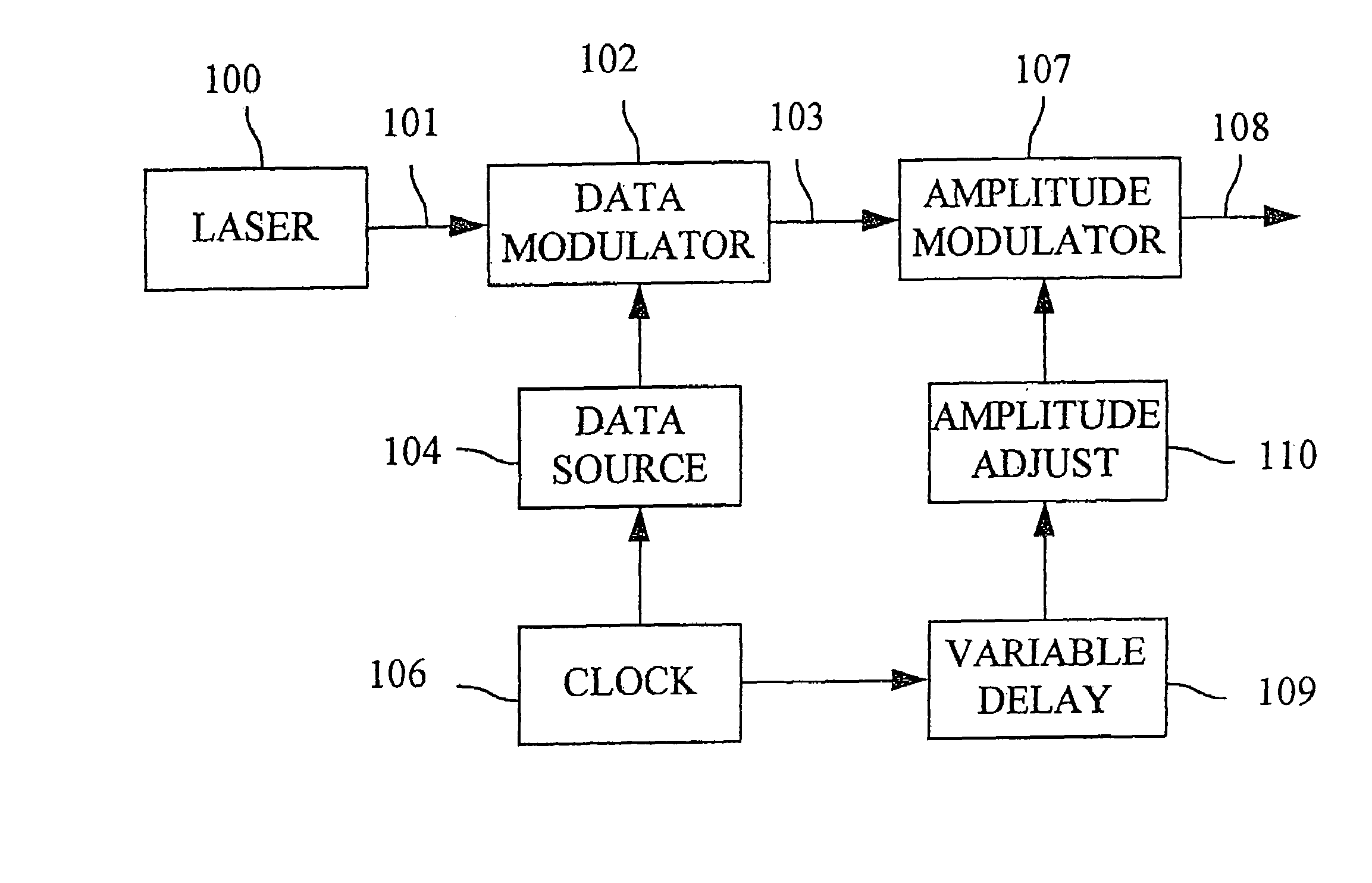
[0015]FIG. 1 shows a simplified block diagram of an exemplary optical transmitter facilitating the practice of the invention. As shown, the invention includes a laser 100 for producing a continuous wave (CW) optical signal 101. The optical signal 101 is transmitted to a data modulator 102 that modulates the signal to impart information thereto in a well known fashion, producing a modulated optical information signal 103. The data modulator 102 receives the data to be imparted to the optical signal 101 from a data source 104 and modulates the optical signal 101 at a frequency determined by a clock 106. The optical information signal 103 is transmitted from the data modulator 102 to an amplitude modulator 107 which places additional intensity modulation on the optical information signal 103. Modulators 102 and 107 could be, for example a 10 Gb / s modulator manufactured by Lucent Technologies as model number 2023.

[0016]In accordance with the present invention, the amplitude modulator 10...


PUM


Abstract

A method and apparatus is provided that yields improved performance of both single channel and WDM long-distance optical transmission systems by synchronously modulating of the transmitted signal's amplitude. An amplitude modulator receives an optical signal onto which data has been modulated at a predetermined frequency. The modulator re-modulates the amplitude of the optical signal in a continuous fashion with a waveform that is periodic, whose fundamental frequency is equal to the same predetermined frequency at which the data is modulated onto the optical signal. The resulting signal (which is neither a pure NRZ or RZ signal) is more tolerant to the distortions usually found in lightwave transmission systems, thus giving superior transmission performance.

Description

CROSS REFERENCE TO RELATED APPLICATIONS[0001]This application is a continuation of U.S. application Ser. No. 10 / 315,560, filed Dec. 10, 2002, now U.S. Pat. No. 6,744,992 which is a continuation of U.S. application Ser. No. 09 / 776,942, filed Jan. 17, 2001, now U.S. Pat. No. 6,556,326, which is a continuation of U.S. application Ser. No. 08 / 771,097, filed Dec. 20, 1996, now abandoned.FIELD OF THE INVENTION[0002]The invention relates to the optical transmission of information and more particularly, to a method and apparatus for improving transmission capabilities over optical fiber transmission systems.BACKGROUND OF THE INVENTION[0003]Very long optical fiber transmission paths, such as those employed in undersea or transcontinental terrestrial lightwave transmission systems, which employ optical amplifier repeaters, are subject to decreased performance due to a host of impairments that accumulate along the length of the optical fiber comprising the transmission path. The source of thes...

Claims


Application Information

Patent Timeline
Patent Type & Authority Patents(United States)
IPC IPC(8): H04B10/04H04B10/00H04B10/135
CPCH04B10/532
Inventor BERGANO, NEAL S.
Owner TYCO ELECTRONICS SUBSEA COMM LLC
Learn More