
Isolator

Inactive Publication Date: 2006-01-19
NEC ELECTRONICS CORP
View PDF4 Cites 0 Cited by
  • Summary
  • Abstract
  • Description
  • Claims
  • Application Information

AI Technical Summary

Benefits of technology

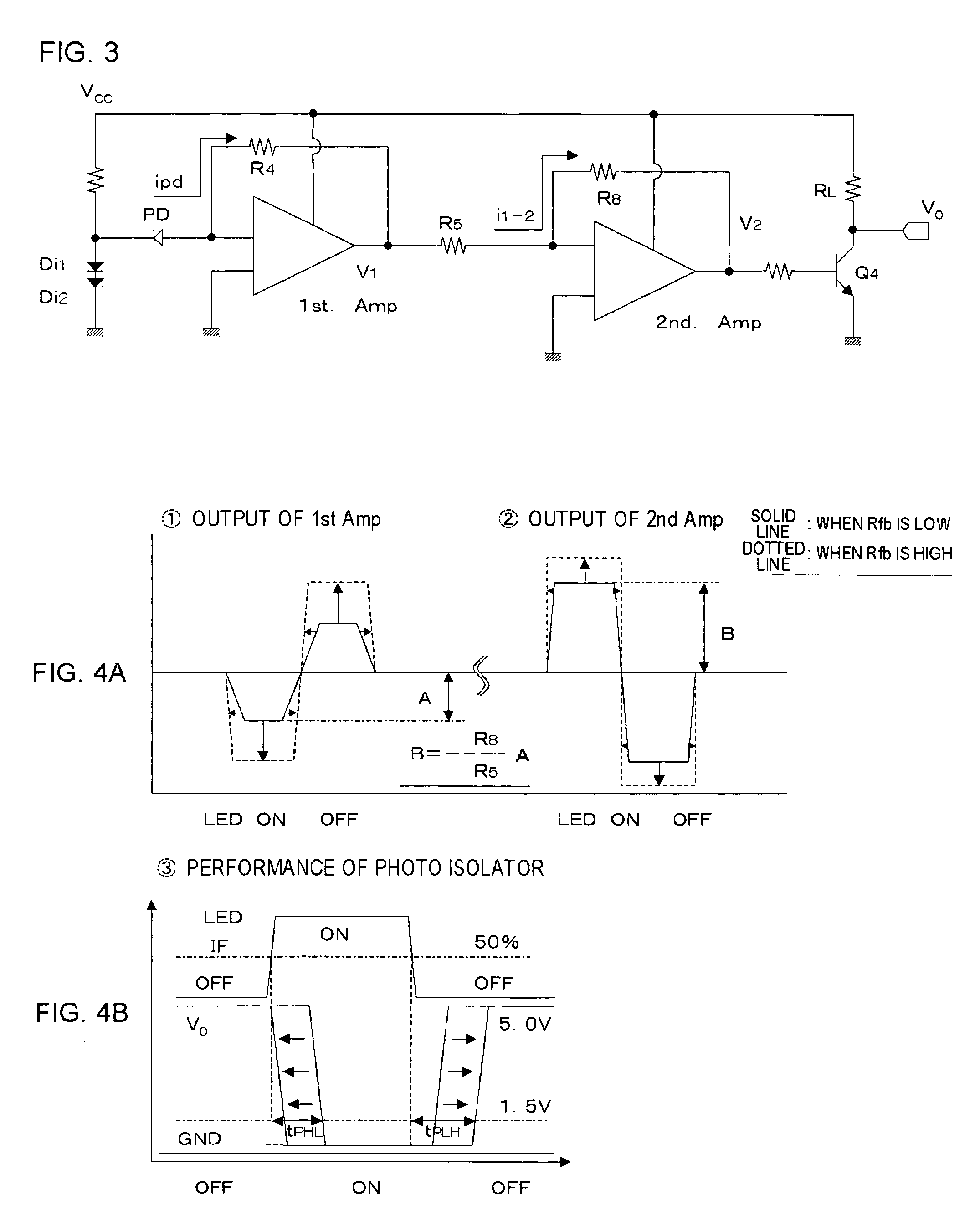
[0015] As shown in FIG. 4A, increasing the Rfb of the respective Amps leads to an increase in output amplitude of the Amps. Accordingly the output current from the Amps also increases, and hence a considerable amount of carrier remains in the base of the associated Tr when the LED turns off. Meanwhile, with respect to a signal transmission delay, the waveshape on the LED-on side quickly falls while the waveshape on the LED-off side delays in rising, in the 1st Amp. In the 2nd Amp, the waveshape on the LED-on side quickly rises, while the waveshape on the LED-off side delays in falling. Consequently, the photo isolator performs so that a tPHL (a delay from the time at which the forward current IF rises to 50% of the rising pulse waveheight of the LED to the time at which the output potential V0 of IC drops to 1.5V) becomes shorter, while a tPLH (a delay from the time at which the forward current IF drops to 50% of the falling pulse waveheight of the LED to the time at which the output potential V0 of IC rises to 1.5V) becomes longer.
[0024] Accordingly, the present invention provides an isolator that allows increasing the amplification factor without compromise in the operating speed.

Problems solved by technology

In a conventional isolator, however, increasing the amplification factor leads to a disadvantage of a reduced operating speed.

Method used


Image

  • Isolator
  • Isolator
  • Isolator

Examples


Embodiment Construction

[0030] The present invention will be now described herein with reference to illustrative embodiments. Those skilled in the art will recognize that many alternative embodiments can be accomplished using the teachings of the present invention and that the invention is not limited to the embodiments illustrated for explanatory purposed.

[0031] Referring to the accompanying drawings, preferred embodiments of the isolator according to the present invention will be described in details hereunder. Same constituents are given an identical numeral in the drawings, and duplicating description will be omitted where appropriate.

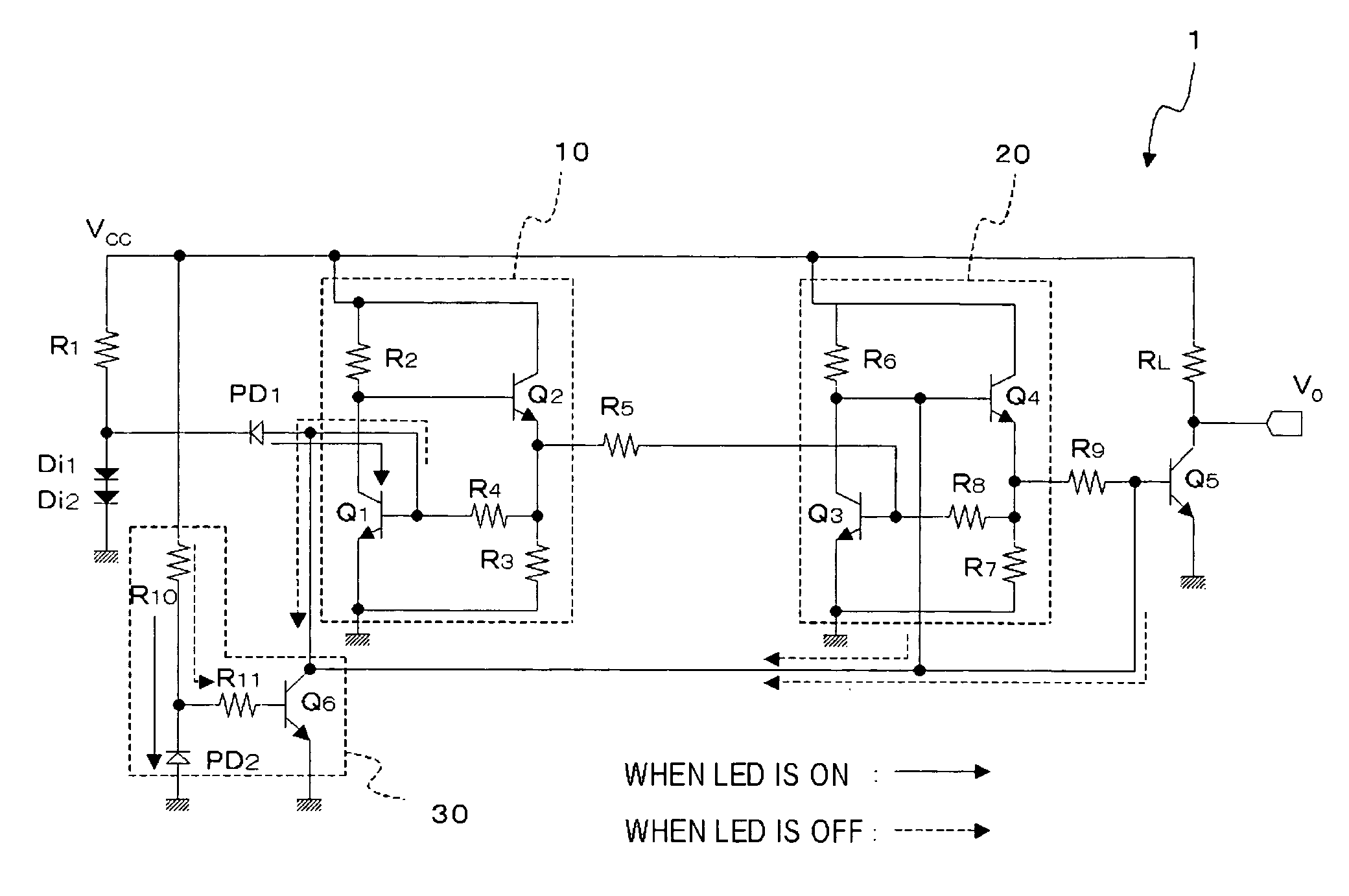
[0032]FIG. 1 is a circuit diagram of an isolator according to an embodiment of the present invention. The isolator 1 is a photo isolator including a photodiode PD1 (first photodiode), amplifiers 10, 20, and a carrier discharging circuit 30.

[0033] The photodiode PD1 is an input element that converts an optical signal input from an LED (signal source, not shown) into an ...


PUM


Abstract

The isolator includes a photodiode (first photodiode), a first and a second amplifier, and a carrier discharging circuit. The photodiode is an input element that converts an optical signal input from an LED (signal source) into an electrical signal, and outputs the electrical signal to the first amplifier. The first amplifier includes two bipolar transistors, and amplifies the electrical signal output by the photodiode. The first amplifier also includes three resistances, one of which is a feedback resistance. The second amplifier has a similar structure to that of the first amplifier. The carrier discharging circuit is connected to the base of the bipolar transistor in the first amplifier and to the base of the bipolar transistor in the second amplifier, so as to discharge, when the photodiode turns off, a carrier accumulated in these bases when the photodiode PD1 is on.

Description

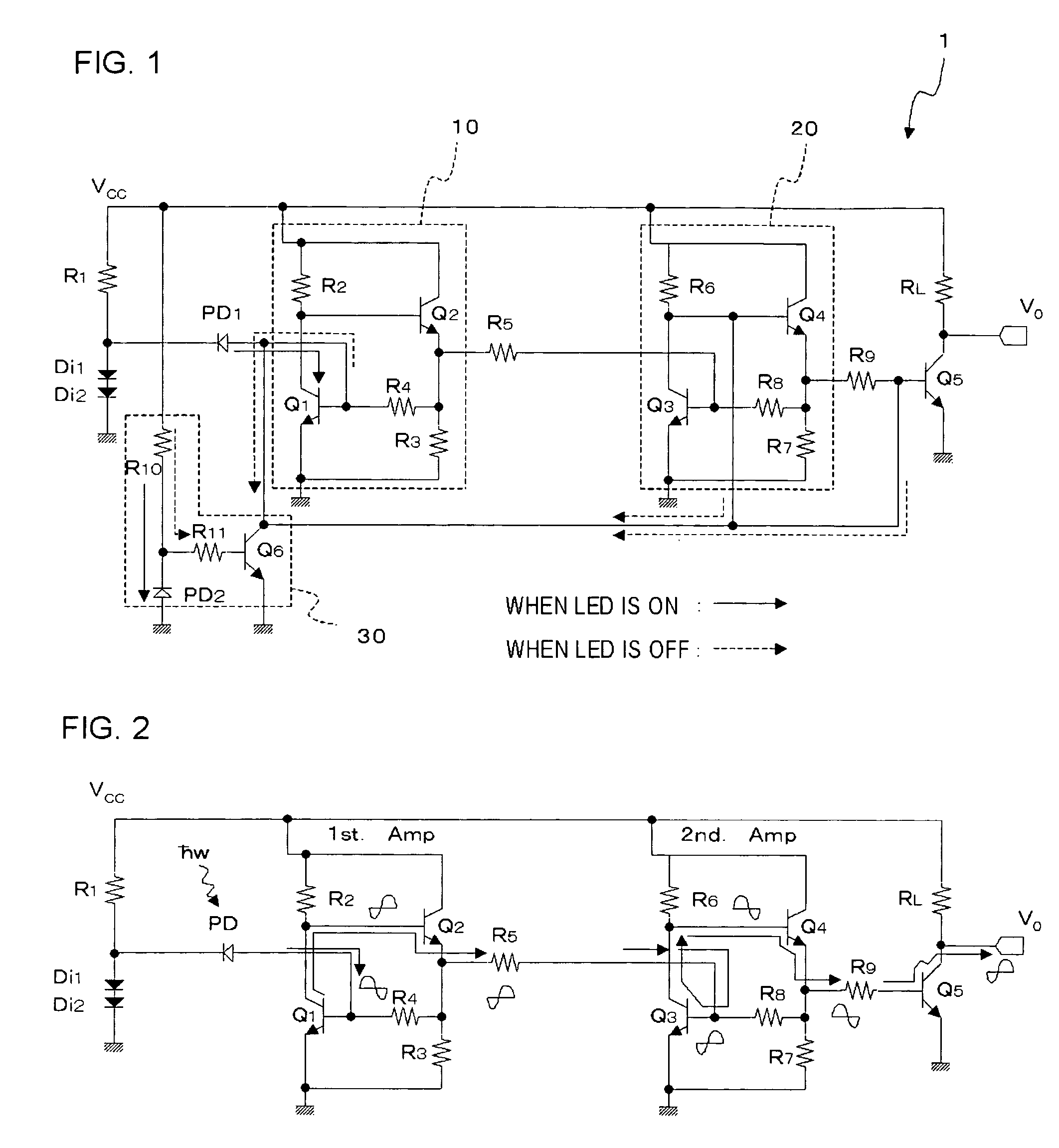
[0001] This application is based on Japanese patent application No. 2004-210770, the content of which is incorporated hereinto by reference. BACKGROUND OF THE INVENTION [0002] 1. Field of the Invention [0003] The present invention relates to an isolator. [0004] 2. Related Art [0005] An isolator is a device that transmits a signal from a signal source such as a light or a magnetic field to a master receiver, and converts the signal into an electrical signal in an IC on the receiving side. With respect to apparatuses such as a servo, an inverter or a color PDP, in which such an isolator outputting a signal to an IC is employed, there has been a demand for an isolator that provides a higher signal transmission speed and a larger overload capacity against a noise such as a source fluctuation or a CMR (a noise which incurs an error in an IC circuit from a displacement current between the signal source and the master receiver). [0006]FIG. 2 is a circuit diagram of a conventional isolator....

Claims


Application Information

Patent Timeline
IPC IPC(8): G02B27/00H03K5/00H03K17/60H03K17/78
CPCH04B10/66
Inventor TAMAI, HIDEFUMI
Owner NEC ELECTRONICS CORP
Learn More