Apparatus and method for sliding-mode control in a multiphase switching power supply

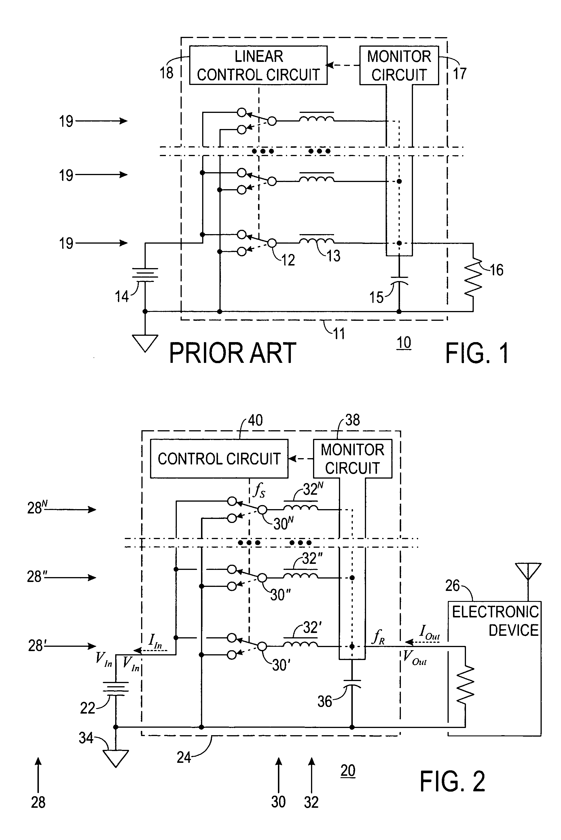
a multi-phase switching power supply and apparatus technology, applied in the field of switching power supplies, can solve the problems of increasing complexity, decreasing reliability, and increasing complexity of the control circuit b>18/b>

Inactive Publication Date: 2006-01-19
INTERSIL INC
View PDF17 Cites 11 Cited by
  • Summary
  • Abstract
  • Description
  • Claims
  • Application Information

AI Technical Summary

Benefits of technology

[0023] Accordingly, it is an advantage of the present invention that an apparatus and method for sliding-mode control in a multiphase switching power supply are provided.
[0024] It is another advantage of the present invention that a multiphase switching power supply is provided that has a control circuit that is simple, reliable, and inexpensive.
[0025] It is another advantage of the present invention that a multiphase switching power supply is provided that requires no more than two state variables, regardless of the number of phases.
[0026] It is another advantage of the present invention that a multiphase switching power supply is provided that is substantially independent of component tolerance.
[0027] It is another advantage of the present invention that a multiphase switching power supply is provided that shares current substantially equally among all phases.
[0028] The above and other advantages of the present invention are carried out in one form by a method of operating a multiphase switching power supply having N phases, where N is an integer greater than one. The method incorporates generating a comprehensive feedback signal from no more than two state variables of the power supply, translating the comprehensive feedback signal into a stream of switching pulses, switching N switches in response to the stream of switching pulses, and effecting one of the N phases with each of the N switches.

Problems solved by technology

However, problems exists with such systems 10 in that, as the number of phases 19 increases, control circuit 18 increases in complexity in order to control and maintain the timing of phases 19.
This increase in complexity is reflected in a decrease in reliability and an increase in cost.
The use of components having typical tolerances may nevertheless result in a wide difference in currents between phases 19, and may result in one switch 12 carrying excessive current.
Consequently, costs associated with control circuit 18 when realized as a linear controller may initially be undesirably high and may be exacerbated by the inability of control circuit 18 to accommodate changes in inductances 13, capacitance 15, and / or load 16.
Conventional implementations of hysteretic controllers, however, are unsuitable for multiphase systems 10.
Even in single-phase systems, hysteretic controllers characteristically exhibit poor performance.
This poor performance is due, at least in part, to the inherent lag between the voltage across capacitance 15 and the current through inductances 13.
Moreover, simply scaling hysteretic or sliding-mode controllers to manage the phase currents of inductances 13, the collective current, and the phase timing for switches 12 in multiphase system 10 produces no significant improvement in complexity over liner controllers, and does not address the problems of reliability and cost.
Allowing ripple frequency to vary makes it difficult to ignore or suppress these effects.
Another problem exists with conventional multiphase switching power supplies utilizing either a hysteretic or sliding-mode control circuit 18 in that, under certain conditions, sudden shifts in load 16 may cause a given switch 12 to enter a lockup condition, i.e., to remain on for an excessive length of time.
Under such circumstances, that switch 12 is in danger of exceeding its tolerances and failing.
Specifically, the current through that switch 12 for that excessive length of time may cause that switch 12 to exceed its power rating, and may thereby cause a catastrophic failure of that switch 12.

Method used


Image

  • Apparatus and method for sliding-mode control in a multiphase switching power supply
  • Apparatus and method for sliding-mode control in a multiphase switching power supply
  • Apparatus and method for sliding-mode control in a multiphase switching power supply

Examples


Embodiment Construction

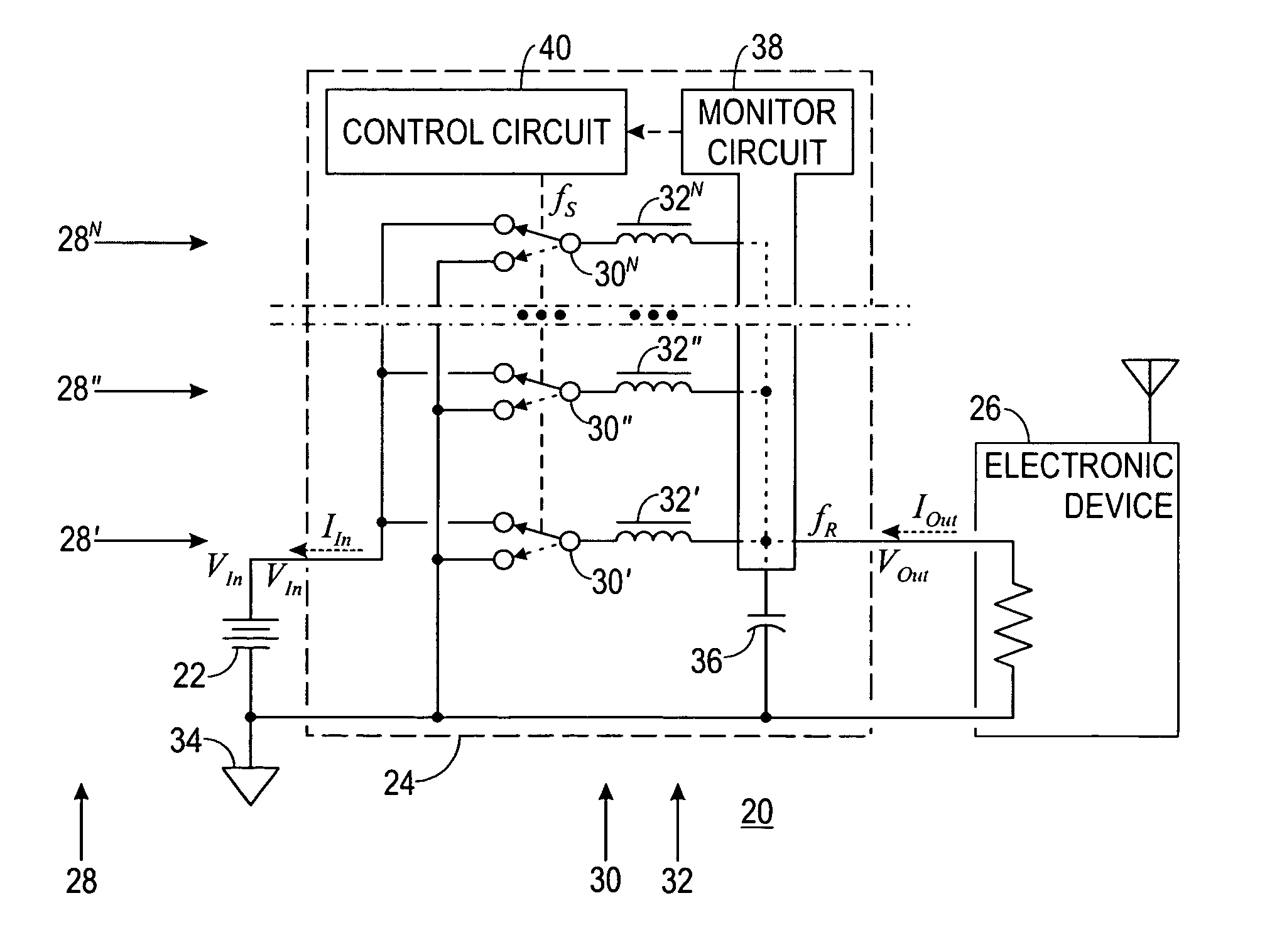
[0039]FIG. 2 shows a simplified schematic diagram of a multiphase system 20 including a D-C power source 22 coupled to a switching power supply 24, which is coupled to a load 26. The following discussion refers to FIG. 2.

[0040] System 20 is made up of power source 22, power supply 24, and load 26. Power source 22 is configured to provide D-C energy in a first form as input energy to power supply 24. This input energy consists of an input voltage VIn at an input current IIn. Power source 22 may be a battery, an A-C to D-C converter, a solar array, a generator, an alternator, or any other source of suitable D-C energy.

[0041] Load 26 demands D-C energy in a second form as output energy from power supply 24. This output energy consists of an output voltage VOut at an output current IOut. Load 26 may be any electronic device, but is often a computing device or a communications device, e.g., a computer, a communications satellite, cellular equipment, or the like.

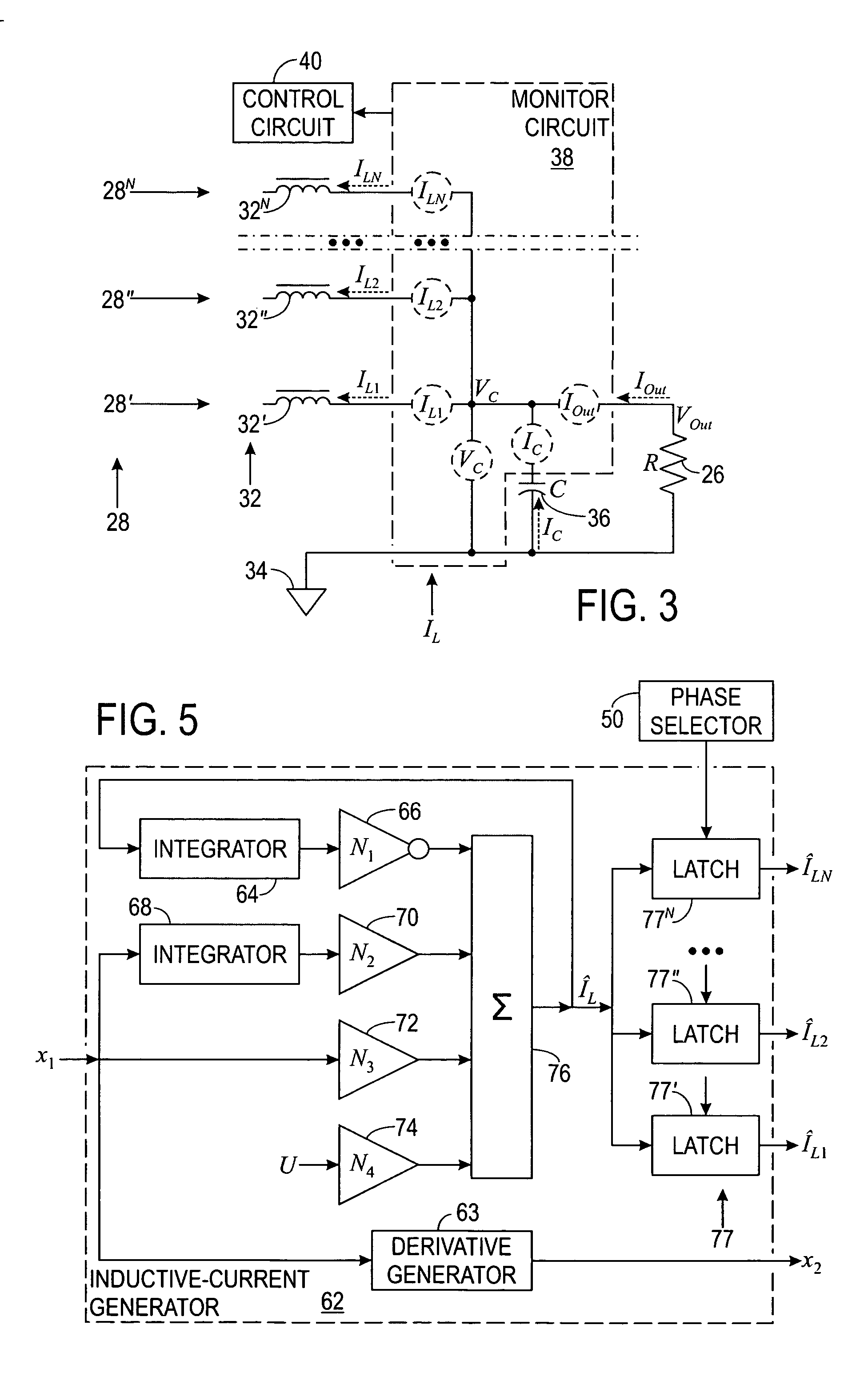
[0042] Power supply 24 ...


PUM


Abstract

A current-sharing multiphase sliding-mode switching power supply (24) and method of operation are presented. A bipolar power source (22) is coupled to a switch (30) for each phase (28), each switch (30) is in turn coupled to an inductance (32), and a capacitance (36) is coupled to the inductances (32) and across a load (26). A sliding-surface generator (78) generates a sliding surface (σ). A current-balance control (80) computes a reference current as a summary statistic (IX) of inductive currents (IL) through the inductances (32), calculates an error current (IE) for each phase (28) as a difference between the summary statistic (IX) and the inductive current (IL), and adjusts the sliding surface (σ) for each phase (28) so that all inductive currents (IL) are substantially equal to the summary statistic (IX). A switching circuit (138) switches the switches (30) in response to the sliding surface (σ).

Description

RELATED INVENTIONS [0001] The present invention claims benefit under 35 U.S.C. 119(e) to “Switching Power Supply with Sliding-Mode Control,” U.S. Provisional Patent Application Ser. No. 60 / 588,098, filed 15 Jul. 2004, which is incorporated by reference herein. [0002] The present invention is related to the following U.S. patent applications, each of which was filed on the same date as the present application, is assigned to the assignee hereof, and is incorporated by reference herein: [0003]“Apparatus and Method for Fixed-Frequency Control in a Switching Power Supply,” by Zaki Moussaoui, U.S. patent application Ser. No. ______; [0004]“Apparatus and Method for State-Variable Synthesis in a Switching Power Supply,” by Zaki Moussaoui, U.S. patent application Ser. No. ______; and [0005]“Apparatus and Method for Transient Control in a Multiphase Switching Power Supply,” by Zaki Moussaoui and Thomas Victorin, U.S. patent application Ser. No. ______.TECHNICAL FIELD OF THE INVENTION [0006] ...

Claims


Application Information

Patent Timeline
Patent Type & Authority Applications(United States)
IPC IPC(8): G05F1/40
CPCH02M3/1584
Inventor MOUSSAOUI, ZAKIALLEN, BRIAN L.PEARCE, LARRY G.
Owner INTERSIL INC
Why Eureka
Try Eureka